Hall effect measurement instrument with temperature compensation

a technology of temperature compensation and measurement instruments, applied in the direction of instruments, resistance/reactance/impedence, material magnetic variables, etc., can solve the problems of not being able to make use of patents, the circuit disclosed is limited to compensating temperature effects, and the measurement could drift with temperature change without the knowledge of the measurement taker or operator

Active Publication Date: 2015-05-21
OLYMPUS AMERICA
View PDF3 Cites 10 Cited by
  • Summary
  • Abstract
  • Description
  • Claims
  • Application Information

AI Technical Summary

Benefits of technology

[0014]It is therefore a primary objective of the present disclosure to provide a Hall Effect instrument with the capability of compensating for temperature drift consistently, accurately and in real time of operation.

Problems solved by technology

As the Hall Effect sensor is located in the probe and sensitive to temperature changes, it presents a unique challenge for the instrument to compensate the temperature of the probe assembly including both magnetic parts and the Hall effect sensor.
It also presents more unique challenges when the operation of a Hall effect sensor based instrument involves interchange of Hall sensor probes and gage and maintaining an accurate and temperature compensated system.
However, since this Ball-Off condition does not always occur, or occur frequently enough, the measurement could drift with temperature change without the knowledge of measurement taker or operator.
However, the circuit as disclosed is limited to compensating temperature effects inside the Hall sensor residing on the same chip.
However, the patent did not make use of the unique property and the subsequent advantages presented by Hall sensors' sensitivity to temperature.
In addition, it explicitly regards the temperature response as linear, which is not an accurate representation of this line of Hall sensor devices.
However, it does not, in Applicant's opinion, directly compensate the temperature effect within the Hall Effect sensor.

Method used


Image

  • Hall effect measurement instrument with temperature compensation
  • Hall effect measurement instrument with temperature compensation
  • Hall effect measurement instrument with temperature compensation

Examples


Embodiment Construction

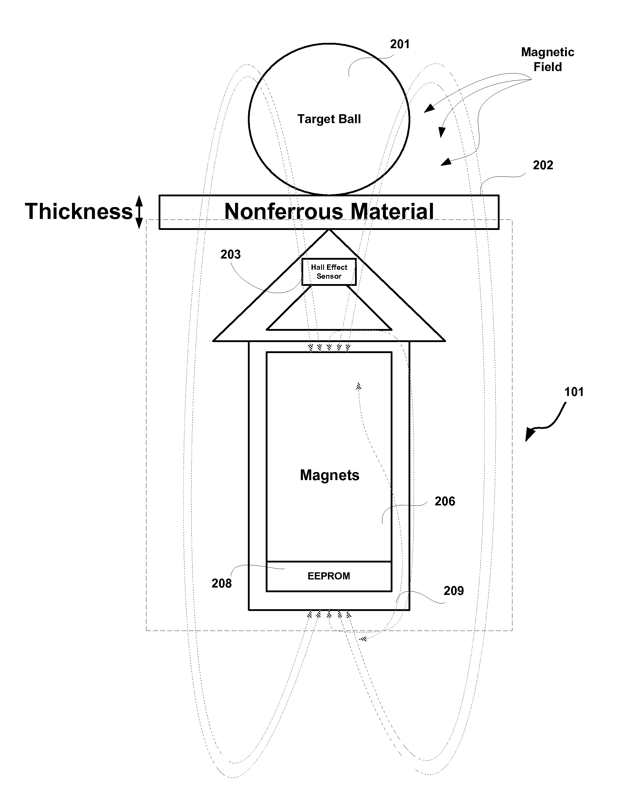
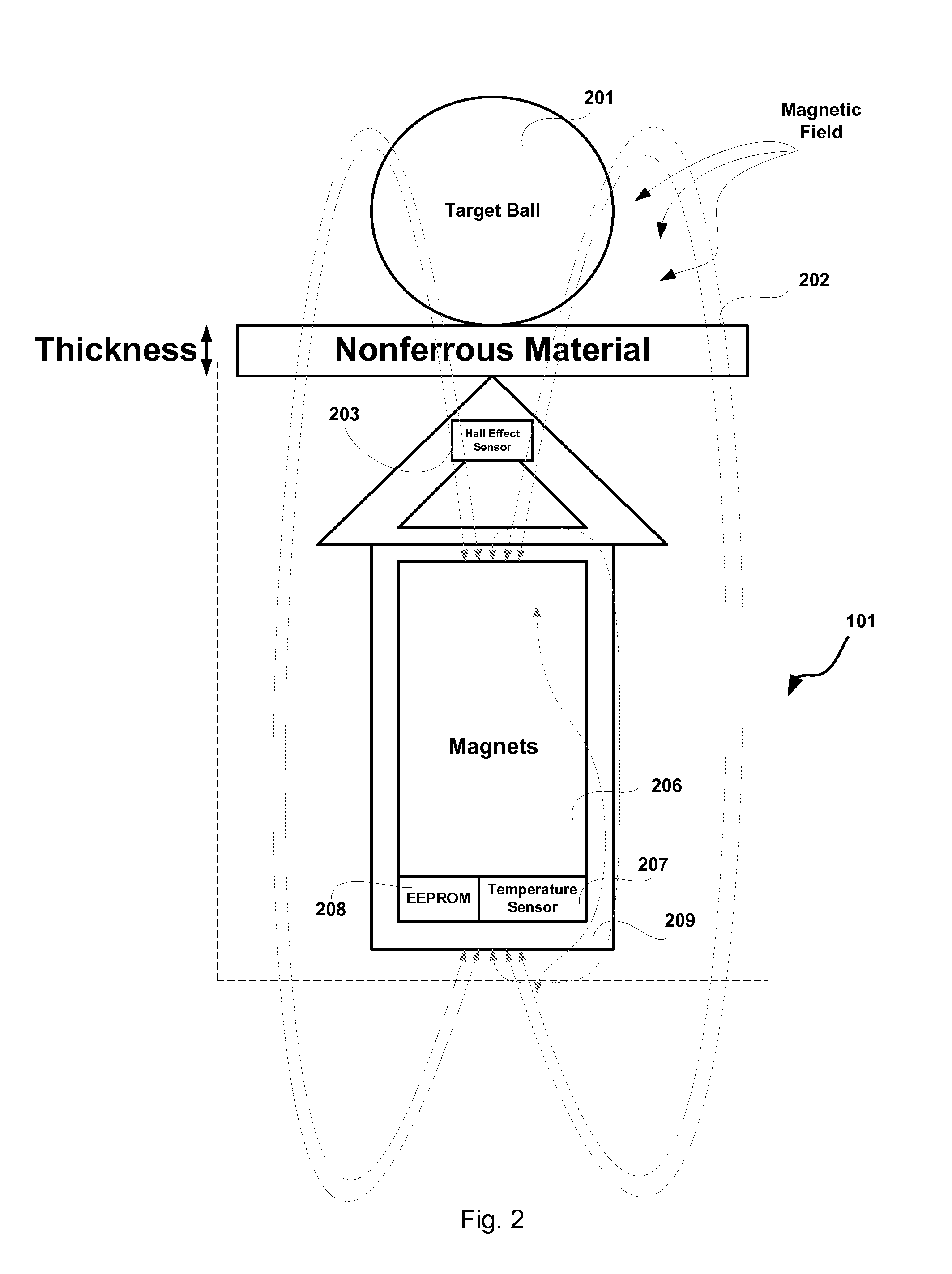
[0030]It should also be noted that some terms commonly used in the industry are interchangeably used in the present disclosure to denote the Hall Effect sensor. For example, “Hall Effect sensor”, “Hall probe” and “Hall sensor”, etc., all denote to the Hall Effect sensor shown as 203 in FIG. 2. It should also be noted that “Hall Effect instrument” or “Hall sensor instrument” denotes to the whole measurement system including the Hall probe, data acquisition circuitry and the whole logic and processing circuitry (not shown). Such variations in the usage of these terms do not affect the scope of the present disclosure.

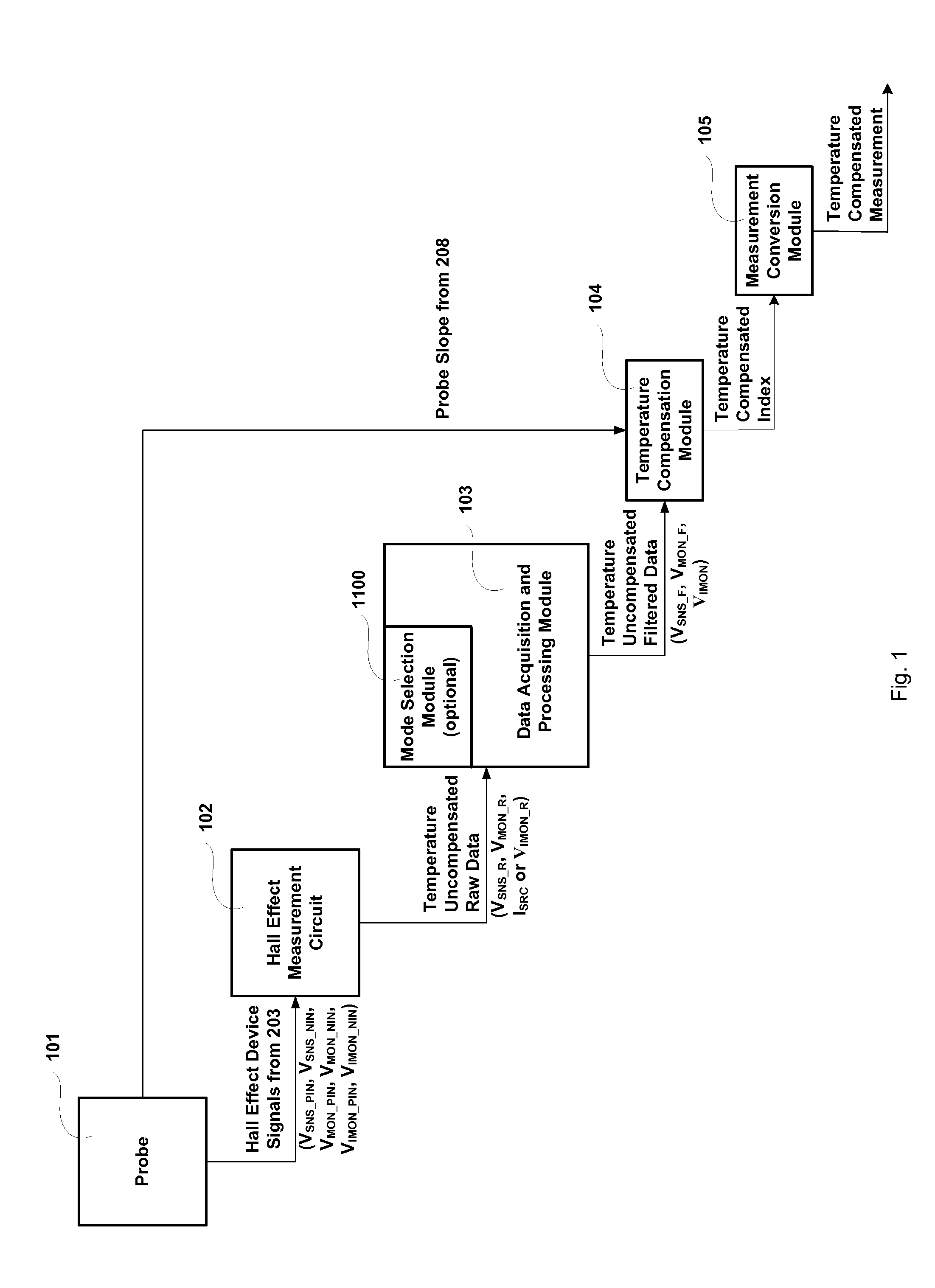
[0031]Referring to FIG. 1, a block diagram of the presently disclosed temperature compensated Hall Effect Sensor Measurement System using a four-wire ohmmeter circuit technique is presented. As can be seen the Hall sensor measurement system includes mainly five modules or five steps used for compensating measurement drift caused by the effect of changes of operational temp...


PUM


Abstract

Disclosed is a Hall Effect instrument with the capability of compensating for temperature drift consistently, accurately and in real time of operation. The instrument embodies a four-point ohmmeter circuit measuring Hall Effect sensor resistance and tracking the effect of temperature on the Hall Effect sensor. The instrument takes into account a relationship between the temperature and a temperature compensation index on a per probe basis, which has exhibited a deterministic difference observed by the present inventor.

Description

CROSS-REFERENCE TO RELATED APPLICATIONS[0001]This application is a Continuation-in-Part of co-pending U.S. application Ser. No. 14 / 077,322 entitled A HALL EFFECT MEASUREMENT DEVICE WITH TEMPERATURE COMPENSATION and filed Nov. 12, 2013, which is herein incorporated by reference.FIELD OF THE INVENTION[0002]The present invention relates to non-destructive testing and non-destructive instruments (NDT / NDI) and more particularly to a Hall Effect probe and measurement device with compensation of measurement drift caused by temperature change.BACKGROUND OF THE INVENTION[0003]Hall Effect sensors have been used in measurement devices such as thickness gages (e.g. Olympus NDT Magna Mike 8500) to accurately measure thickness of nonferrous materials. One of the most often seen applications is thickness measurement on plastic bottles. A Hall Effect sensor typically comprises a probe that has magnet(s) generating a primary magnetic field. Measurements are performed by holding the device's magnetic...

Claims


Application Information

Patent Timeline
Patent Type & Authority Applications(United States)
IPC IPC(8): G01R33/07G01R35/00
CPCG01R35/00G01R33/072G01B7/10G01D3/0365G01D5/142G01R1/44G01R33/0035G01R33/0082
Inventor THOMAS, ANDREWBESSER, STEVEN
Owner OLYMPUS AMERICA
Why Eureka
Try Eureka