Filtration apparatus

a technology of filtration apparatus and filtration media, which is applied in the direction of moving filter element filter, stationary filter element filter, water/sludge/sewage treatment, etc., can solve the problems of increasing the cost of the vessel, increasing the potential risk of leakage between the chambers, and reducing the efficiency of filtration media such as membranes, so as to facilitate the distribution of feed fluid, facilitate the distribution of substantially even gas, and facilitate the effect of distribution

Active Publication Date: 2015-05-28
VEOLIA WATER SOLUTIONS & TECH SUPPORT
View PDF7 Cites 7 Cited by
  • Summary
  • Abstract
  • Description
  • Claims
  • Application Information

AI Technical Summary

Benefits of technology

[0098]The tubular members may facilitate distribution, for example even distribution, of a fluid from the third chamber into the filtration modules. For example, the tubular members may facilitate distribution of a feed fluid or a fluid to be treated.
[0099]The tubular mem

Problems solved by technology

Accordingly, the size and number of the holes can significantly weaken the plate and as a result partition plates are typically formed to be relatively thick, which can increase the cost of the vessels, particularly where expensive materials, such as titanium, are required, for example to resist corrosive chemicals which may be present in the vessel.
Furthermore, as the individual holes in a partition plate are dimensioned to accommodate the full width of the filtration modules, the required sealing area to maintain isolation between upper and lower chambers can also be relatively large, increasing the potential risk of leakage between chambers.
The efficiency of filtration media such as membranes will reduce over time due to fouling, which typically results in an increase in the pressure drop across the media.
However this type 1 clean does not fully clean the membrane and as such there is a slow increase in the pressure drop across the “cleaned” membrane.
A type 2 clean, however, typically still does not fully clean the membrane, such that over a longe

Method used


Image

  • Filtration apparatus
  • Filtration apparatus
  • Filtration apparatus

Examples


cleaning example 3

Forwardwashinq

[0213]In certain circumstances cleaning of the membranes may be achieved by forward flow of a washing fluid through the modules. In one configuration the forward washing fluid may pass through the membranes in a conventional filtering direction.

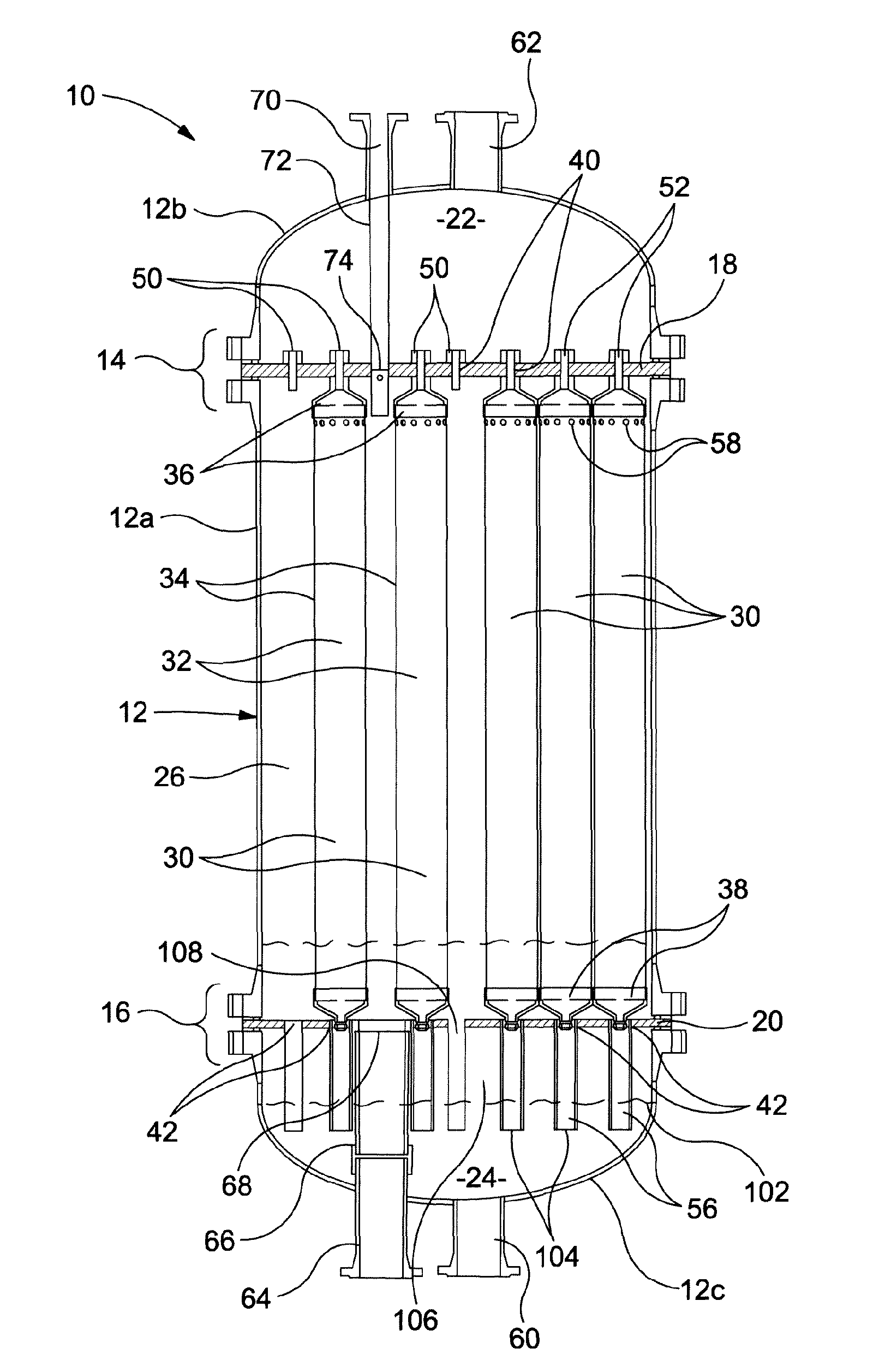
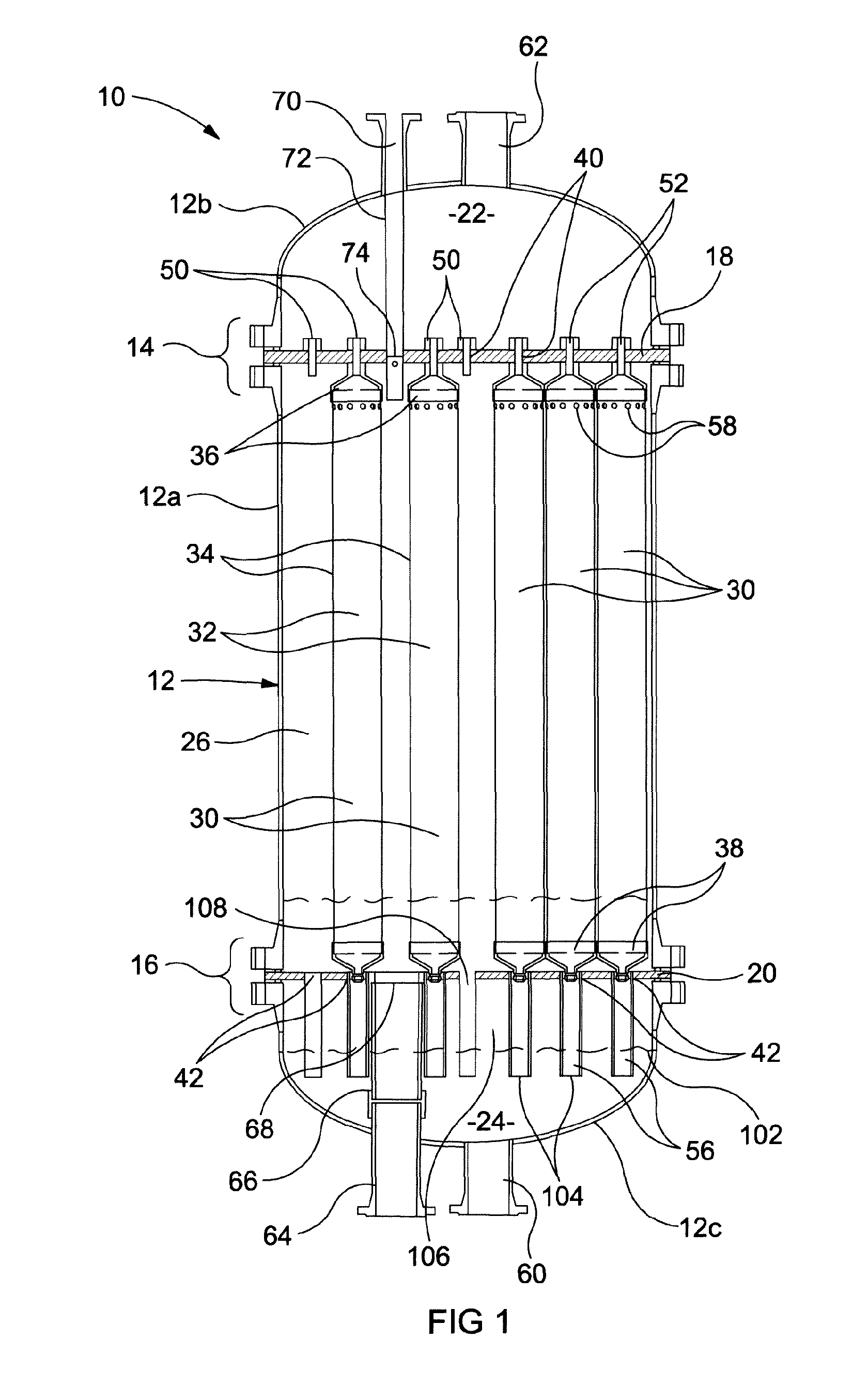
[0214]In another configuration the forward washing fluid may be cross-flowed over the surface of the membranes thus dislodging particulate and other material. That is, fluid may be passed over the surface of the membranes without, or with a minimal volume, passing through the membranes. The exemplary embodiment disclosed permits such cross-flow forwardwashing by virtue of the lower and intermediate chambers 24, 26 being isolated from each other.

[0215]To achieve forwardwashing valve 82 may be opened to permit raw water to flow into the third chamber via port 60, into the modules 30 and across the surfaces of the membranes, with the forwardwashed water containing dislodged material exiting into the intermediate chamber 26 via shro...

cleaning example 4

Simultaneous Backwashing and Forwardwashing

[0218]The filtration apparatus in the disclosed exemplary embodiment may also support both forwardwashing and backwashing to be achieved simultaneously. Such may be achieved by opening valve 76 to permit permeate to be backwashed through the modules, opening valve 82 to permit raw water to be forwardwashed through the modules and across the membrane surfaces, and opening valve 78 to permit dirty forwardwashed and backwashed water to be drained from the intermediate chamber 26. All other valves may be configured appropriately.

[0219]As a variation, forwardwashing fluid may be provided by permeate which is diverted through port 60 via an appropriate valve arrangement.

cleaning example 5

Chemically Enhanced Washing

[0220]In certain circumstances it may be desired to expose the membranes to a chemical to facilitate cleaning, for example to dissolve particulate matter, destroy bacterial growth and the like.

[0221]In one example a Chemically Enhanced Backwashing (CEB) may be utilised. Such CEB may be achieved in one example by opening valve 83 to permit a chemical, such as hypochlorite, to be dosed into backwashing permeate water and delivered into the vessel via port 62, with all other ports and valves configured appropriately for backwashing, as defined in Example 1 (or Example 2) above.

[0222]Furthermore, as the embodiment disclosed herein also permits forwardwashing to be achieved, as defined in Example 3 above, it is also possible in a variation to enhance such forward washing by dosing a chemical, such as hypochlorite into the raw water, or permeate, which is delivered into the vessel via port 60, with an appropriate piping and valve arrangement. Of course, simultan...


PUM

PropertyMeasurementUnit
Pressureaaaaaaaaaa
Widthaaaaaaaaaa
Levelaaaaaaaaaa

Abstract

A filtration apparatus (10) for treating a fluid comprises a vessel (12), a first partition plate (18) dividing the vessel into first and second chambers (22, 26) and defining a through hole (40), and a filtration module (30) located within the second chamber (26) and including a body section (32) defining an outer diameter which is greater than the diameter of the through hole (40) in the first partition plate (18). The apparatus (10) further comprises a reducing connector (36) having a first end secured to the body section (32) of the filtration module (30) and a second end sealed relative to the through hole (40) in the first partition plate (18) to permit communication between the filtration module (30) and the first chamber (22).
In a disclosed embodiment the apparatus (10) includes a second partition plate (20) such that the vessel is divided into first, second and third chambers (22, 24, 26), wherein the filtration module (30) is mounted between the partition plates (18, 20).

Description

[0001]This application is a U.S. National Stage Application of PCT Application No. PCT / EP2013 / 060647, with an international filing date of 23 May 2013. Applicant claims priority based on United Kingdom Patent Application No. 1209327.4 filed 23 May 2012. The subject matter of these applications is incorporated herein.FIELD OF THE INVENTION[0002]The present invention relates to a filtration apparatus, and in particular to a filtration apparatus which includes one or more filtration modules contained within a vessel.BACKGROUND TO THE INVENTION[0003]Filtration is well known for the treatment of fluids, such as water, and is typically achieved by use of appropriate filtration media, such as filtration membranes. A conventional arrangement for housing and utilising filtration membranes is to arrange each membrane unit (hereafter called a “module”) into its own pressure containing housing which has suitable connections to allow filtration and cleaning cycles to be performed on the membrane...

Claims


Application Information

Patent Timeline
IPC IPC(8): B01D63/06B01D63/04B01D65/02
CPCB01D63/06B01D65/02B01D63/046B01D63/061B01D2313/13B01D2321/16B01D2321/04B01D2321/18B01D2317/04B01D29/52B01D65/00B01D65/08B01D2201/043B01D2313/02B01D2313/20B01D2313/26B01D2321/02B01D2321/185B01D2201/0453Y10T29/49826B01D29/00B01D33/48B01D35/30B01D35/306B01D39/00
Inventor LANGE, NEVILLE ERNEST
Owner VEOLIA WATER SOLUTIONS & TECH SUPPORT
Why Eureka
Try Eureka