Low-loss step-up and step-down voltage converter

a voltage converter and step-down technology, applied in the field of low-loss step-up and step-down voltage converters, can solve the problems of increasing conduction losses through these power fets, significant switching losses in these power fets, and significant resistance losses through the power fet implementing the always-closed switch swb>4/b> in the buck mode, so as to achieve significant resistance losses

Active Publication Date: 2015-05-28
TEXAS INSTR INC
View PDF26 Cites 30 Cited by
  • Summary
  • Abstract
  • Description
  • Claims
  • Application Information

AI Technical Summary

Benefits of technology

[0013]Embodiments of this invention provide a switch-mode DC-DC voltage converter that is operable in step-down (“buck”...

Problems solved by technology

Because each of these switches SW1 through SW4 are switched twice per cycle, the switching losses in these power FETs can be significant.
In addition, conduction losses through these power FETs incre...

Method used


Image

  • Low-loss step-up and step-down voltage converter
  • Low-loss step-up and step-down voltage converter
  • Low-loss step-up and step-down voltage converter

Examples


Embodiment Construction

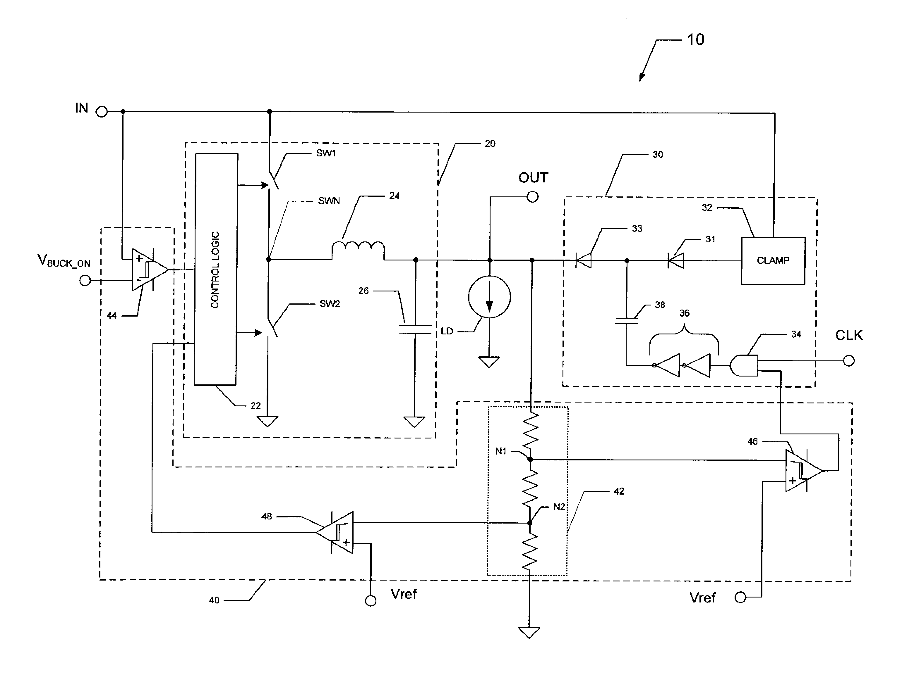
[0023]This invention will be described in connection with its embodiments, namely as implemented into a switch-mode DC-DC voltage converter realized in an integrated circuit. It is to be understood that the following description is provided by way of example only, and is not intended to limit the true scope of this invention as claimed.

[0024]FIG. 3 illustrates, in a general sense, the construction of switch-mode DC-DC voltage converter 10 according to embodiments of the invention. As mentioned above, it is contemplated that voltage converter 10 will typically be realized in a monolithic integrated circuit, generally embedded within a larger-scale integrated circuit along with other functions, but alternatively as a stand-alone integrated circuit. Alternatively, it is contemplated that some or all of the components of voltage converter 10 may be realized by discrete components. As shown in FIG. 3, voltage converter 10 includes a step-down converter in the form of buck converter stage...


PUM


Abstract

A switch-mode DC-DC voltage converter including a boost stage in the form of a charge pump and a buck stage. Control circuitry is provided that enables the operation of the buck stage while the charge pump stage is also enabled, followed by disabling of the charge pump stage as the input voltage and output voltage increase. The buck converter stage is constructed so that it regulates the output voltage at a voltage above that which disables the charge pump stage. Conduction losses in the main current path, due to the necessity of a power FET or other switching device, are avoided.

Description

CROSS-REFERENCE TO RELATED APPLICATIONS[0001]Not applicable.STATEMENT REGARDING FEDERALLY SPONSORED RESEARCH OR DEVELOPMENT[0002]Not applicable.BACKGROUND OF THE INVENTION[0003]This invention is in the field of voltage converters. Embodiments of the invention are more specifically directed to DC-DC switch-mode voltage converters, such as are used in DC power supplies and DC motor drive applications, and the like.[0004]Voltage converter circuits are common components of many electrical and electronic systems having loads that are to be driven by regulated DC voltages. For example, many electronic systems include integrated circuits and other loads that require a relatively stable DC voltage. As such, these systems typically include a DC power supply for converting unregulated DC input power received from a battery, or from an AC line voltage via a rectifier, into a stable regulated DC power output to be applied to the integrated circuit or other system loads, such as a DC motor.[0005...

Claims


Application Information

Patent Timeline
IPC IPC(8): H02M3/158H02M3/157H02M1/00
CPCH02M3/157H02M3/158H02M3/07H02M3/1582H02M3/1584H02M1/0048Y02B70/10
Inventor TORRES, ERICK OMARVENKATARAMAN, HARISHJANG, BYUNGCHUL
Owner TEXAS INSTR INC
Why Eureka
Try Eureka