Optical compensation film for liquid crystal display and liquid crystal display including the same

a liquid crystal display and optical compensation technology, applied in non-linear optics, instruments, optics, etc., can solve the problems of limiting the contrast ratio of liquid crystal displays, serious light leakage, and greatly affecting the sharpness of images under some viewing angles, so as to reduce light leakage, increase contrast, and reduce light leakage

Inactive Publication Date: 2015-05-28
TCL CHINA STAR OPTOELECTRONICS TECH CO LTD
View PDF8 Cites 12 Cited by
  • Summary
  • Abstract
  • Description
  • Claims
  • Application Information

AI Technical Summary

Benefits of technology

[0007]Aiming at improving the effect for reducing light leakage using a compensation film on a liquid crystal display, the present disclosure proposes an optical compensation film for a liquid crystal display, for reducing light leakage and increasing contrast.
[0008]Through research, inventors find that the compensation values of a C-plate and an A-plate in the compensation film are directly related to the effect for reducing light leakage by the compensation film, wherein a better effect for reducing light leakage can be obtained though the in-plane compensation value (RoA-plate) for optical path difference of the A-plate, the compensation value for optical path difference in the thickness direction (RthA-plate) of the A-plate and the compensation value for optical path difference in the thickness direction (RthC-plate) of the C-plate in the compensation film in respective specific ranges and in cooperation with one another.
[0014]According to embodiment 1, the light leakage in dark status which may occur in the prior art can be effectively reduced without impairing the transmittance of the liquid crystal panel, resulting in an increase of the contrast ratio and sharpness of the images under a large viewing angle, which is not in the horizontal or vertical azimuth.
[0029]Experiments shows that the light leakage distribution can be greatly reduced, so that the present disclosure has significant advantages compared with the prior art as long as the A-plate and the C-plates are within the compensation value ranges in the technical solutions of the present disclosure. The experiments will be discussed in detail with reference to the accompanying drawings below. Meanwhile, the contrast ratio can be increased and the range of viewing angle can be significantly broadened, with clear images to be received under large viewing angles.

Problems solved by technology

Generally, the insufficient dark state is a main factor limiting the contrast ratio of the liquid crystal display.
Thus it could be seen that when A-plate and C-plate compensation values in the prior art are adopted, a serious light leakage would occur when viewing is taken in a dark state under a large angle.
As a result, the sharpness of images would be greatly affected under some viewing angles.

Method used


Image

  • Optical compensation film for liquid crystal display and liquid crystal display including the same
  • Optical compensation film for liquid crystal display and liquid crystal display including the same
  • Optical compensation film for liquid crystal display and liquid crystal display including the same

Examples


example 1

[0073]

optical pathpre-tiltdifferenceangle ofin liquidliquidA-plateA-platethe sum ofcrystalcrystalRoRthC-plate Rth333.5 nm89 degrees132 nm66 nm179 nm

[0074]FIG. 6 shows a diagram of dark-state full-view light leakage distribution in Example 1, and FIG. 7 shows a diagram of full-view contrast distribution in Example 1.

example 2

[0075]

optical pathpre-tiltdifferenceangle ofin liquidthe liquidA-plateA-platethe sum ofcrystalcrystalRoRthC-plate Rth333.5 nm89 degrees132 nm66 nm206 nm

[0076]FIG. 8 shows a diagram of dark-state full-view light leakage distribution in Example 2, and FIG. 9 shows a diagram of full-view contrast distribution in Example 2.

example 3

[0077]

optical pathpre-tiltdifferenceangle ofin liquidthe liquidA-plateA-platethe sum ofcrystalcrystalRoRthC-plate Rth333.5 nm89 degrees132 nm66 nm266 nm

[0078]FIG. 10 shows a diagram of dark-state full-view light leakage distribution in Example 3, and FIG. 11 shows a diagram of full-view contrast distribution in Example 3.

[0079]In FIG. 6 to FIG. 11:

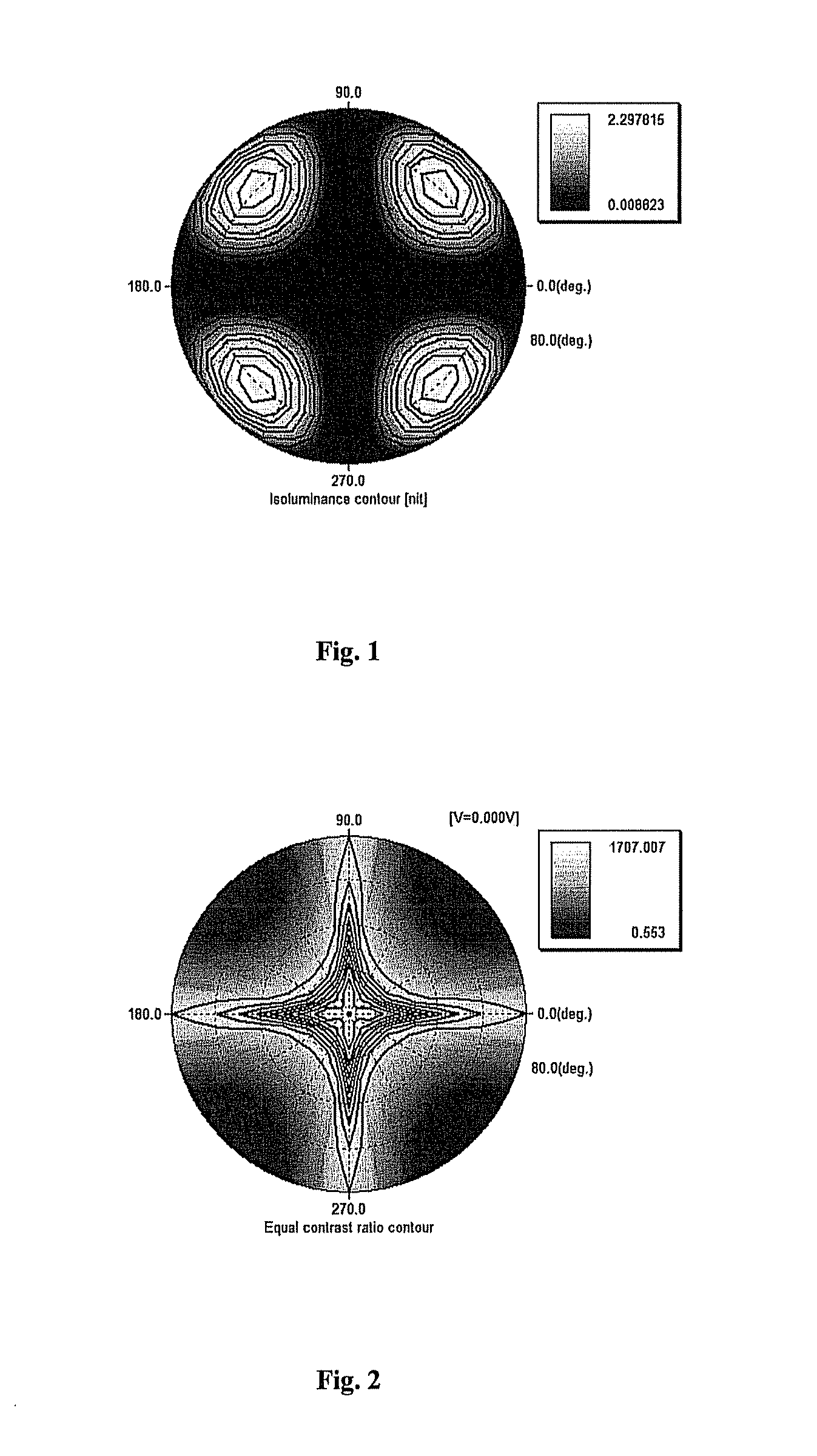
maximumminimumlightlightmaximumminimumleakage (nit)leakage (nit)contrastcontrastComparative2.2978150.0088231707.0070.553exampleExample 1:0.1877430.0077461715.62313.075Example 20.0505350.0085141707.92944.285Example 30.1940540.0088061742.3476.412

[0080]By comparing FIG. 6, FIG. 8 and FIG. 10 corresponding to Example 1, Example 2 and Example 3 respectively with FIG. 1, it could be found that after the compensation values of the A-plate and the C-plates of the optical compensation film are adjusted, the maximum dark-state light leakage is reduced from 2.3 nits to 0.2 nit or below, which is far lower than the dark-state light leakage obtained wi...


PUM

PropertyMeasurementUnit
optical path differenceaaaaaaaaaa
thicknessaaaaaaaaaa
pre-tilt angleaaaaaaaaaa

Abstract

The present invention relates to liquid crystal display technology, and provides an optical compensation film for a liquid crystal display, including a first polarizer and a second polarizer disposed on both sides of the liquid crystal panel respectively, and an A-plate and a C-plate arranged between the liquid crystal panel and the first polarizer or between the liquid crystal panel and the second polarizer, wherein the in-plane compensation value for optical path difference of the A-plate RoA-plate lies in the range of [92, 184]nm, the compensation value for optical path difference in the thickness direction of the A-plate RthA-plate lies in the range of [46, 92]nm. The dark-state light leakage distribution and the contrast ratio of the display are improved through the optical compensation film according to the invention. The invention further provides a liquid crystal display including an optical compensation film.

Description

FIELD OF THE INVENTION[0001]The present disclosure relates to the technical field of liquid crystal display, and particularly, relates to an optical compensation film for a liquid crystal display and the liquid crystal display including the same.BACKGROUND OF THE INVENTION[0002]The contrast ratio of a liquid crystal display, directly related with its adaptability, significantly affects how it would be accepted by the market. The contrast ratio is a ratio of the luminance of the brightest color (white) to that of the darkest color (black) of the display. Generally, the insufficient dark state is a main factor limiting the contrast ratio of the liquid crystal display. With the increase of a viewing angle of a thin film transistor-liquid crystal display (TFT-LCD), the contrast ratio of pictures is continually reduced, and the sharpness of the pictures also correspondingly declines. This is due to the fact that the birefringence of liquid crystal molecules in a liquid crystal layer is c...

Claims


Application Information

Patent Timeline
Patent Type & Authority Applications(United States)
IPC IPC(8): G02F1/13363G02F1/1335
CPCG02F1/133634G02F2001/133531G02F1/13363G02F1/133528G02F2413/02G02F2413/05G02F2413/08G02F1/133531
Inventor KANG, CHIH-TSUNGHAI, BO
Owner TCL CHINA STAR OPTOELECTRONICS TECH CO LTD
Why Eureka
Try Eureka