Surge protector for a transmission line connector

a transmission line connector and surge protector technology, applied in the direction of overvoltage protection resistors, emergency protective arrangements for limiting excess voltage/current, and arrangements responsive to excess voltage, etc., to achieve the effect of improving return loss

Inactive Publication Date: 2015-05-28
THOMSON LICENSING SA
View PDF4 Cites 8 Cited by
  • Summary
  • Abstract
  • Description
  • Claims
  • Application Information

AI Technical Summary

Benefits of technology

[0006]A network for applying a source of a radio frequency (RF) signal to a signal processing stage, forming a load with respect to the network, includes a first inductor coupled to the load. A transmission line connector is responsive to the RF signal and coupled to the first inductor for coupling the RF signal to the load, during normal operation. The connector is susceptible to couple a surge voltage to the first inductor, when the surge voltage occurs. The network includes a surge suppressing threshold device and a second inductor coupled to the connector for coupling the surge suppressing threshold device to the connector to suppress the surge voltage, when the surge voltage causes the surge suppressing threshold device to turn on. A capacitor is coupled to the second inductor to form a parallel resonant circuit for improving return loss at an interface of the network with one of the RF signal source and the load.

Problems solved by technology

The connector is susceptible to couple a surge voltage to the first inductor, when the surge voltage occurs.

Method used


Image

  • Surge protector for a transmission line connector
  • Surge protector for a transmission line connector
  • Surge protector for a transmission line connector

Examples


Embodiment Construction

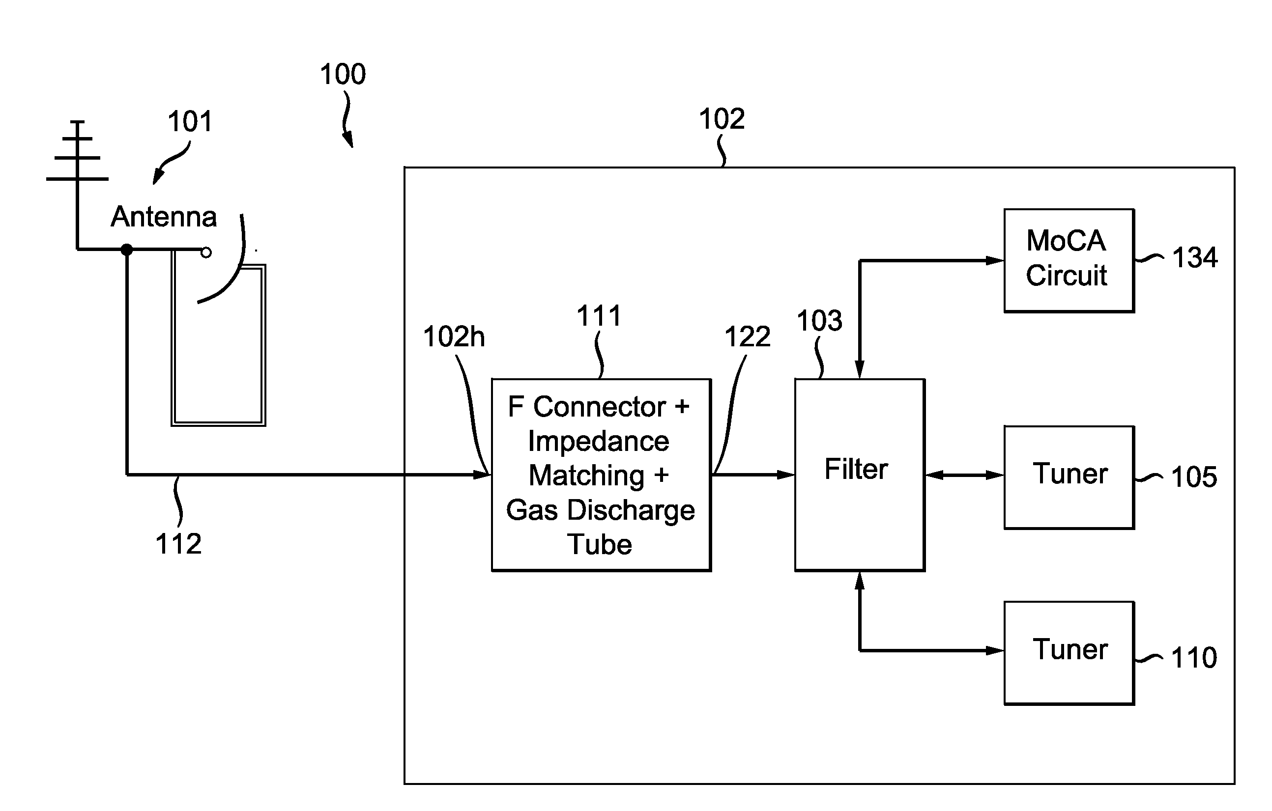
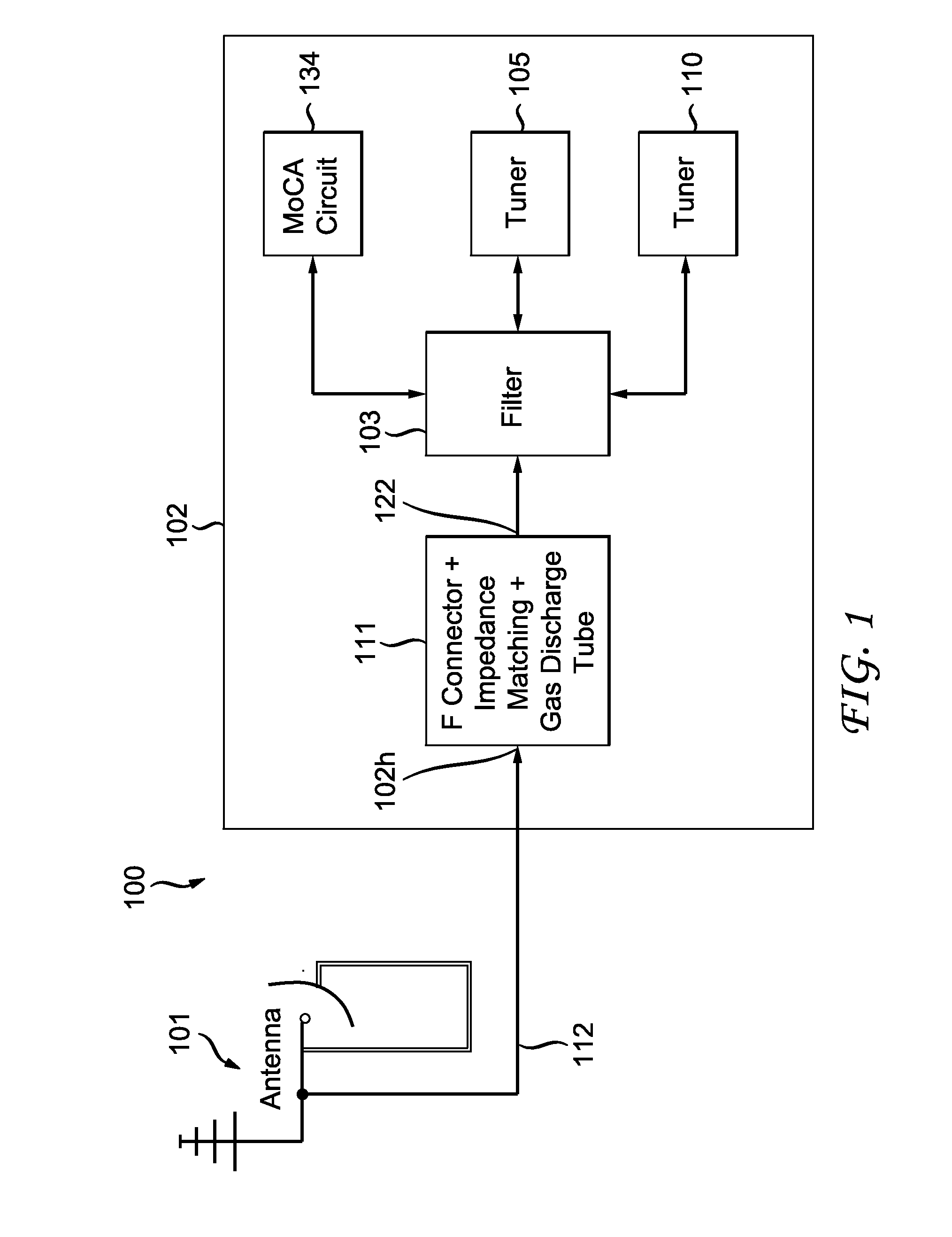
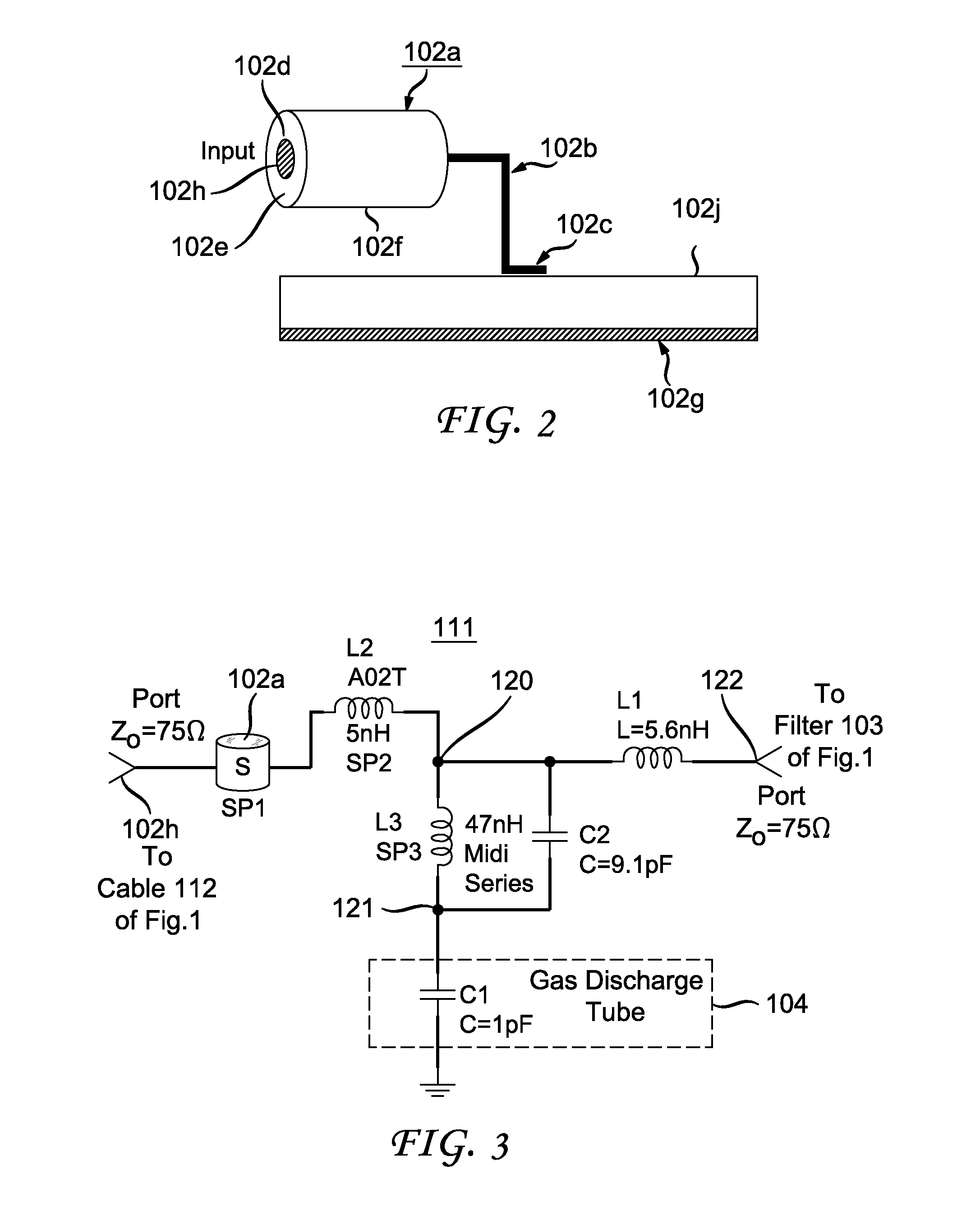
[0012]FIG. 1 illustrates, partially in a block diagram, a signal receiving device 100 forming, for example, a set-top box 102, that includes a network 111, embodying an inventive feature.

[0013]Signal receiving device 100 primarily receives signals from one or more satellites as well as multiple television broadcast transmission sites, not shown. The signals are provided by one or more service providers and represent broadcast audio and video programs and content. Signal receiving device100 includes components that reside for satellite reception both inside and outside a user's premises. In cable reception the components may reside only inside a user's premises. One or more components may be integrated with a display device, such as a television or display monitor, not shown. An outdoor unit (ODU) 101 receives signals from satellites and from terrestrial transmission towers through an over the air and / or near earth orbit communications link. ODU 101 is connected to set top box 102 vi...


PUM


Abstract

An F connector coupled to a transmission line applies a radio frequency (RF) signal to an RF input of a filter of a set-top box via an impedance matching network that includes a first inductor and a second inductor that are coupled in series. A capacitor and a third inductor are coupled in parallel between a discharge tube and a junction terminal that is interposed between the series coupled inductors for protecting electronic components such as the filter from a voltage surge developed in the transmission line.

Description

FIELD OF THE INVENTION[0001]The invention relates to a surge protector coupled to a transmission line connector.BACKGROUND OF THE INVENTION[0002]A radio frequency (RF) input signal is typically applied to an input of a home entertainment device, for example, a set-top box via an external coaxial cable, for example, a[0003]Multimedia over Coax Alliance (MoCA) cable, having a terminating coaxial connector known as F connector. The set-top box contains electronic components which may be vulnerable to damage from electrical surges. Surges in transmission line voltages, as well as noise, can change the operating range of the components and severely damage and / or destroy them. There are many sources which can cause harmful electrical energy surges. One source is RF interference that can be coupled to transmission lines from a multitude of sources. The transmission lines act as large antennas that may extend over several miles, thereby collecting a significant amount of RF noise power from...

Claims


Application Information

Patent Timeline
Patent Type & Authority Applications(United States)
IPC IPC(8): H02H9/08H04M3/18
CPCH04M3/18H02H9/08H02H9/041H02H9/06H02H9/046H05K1/0257H02H9/04
Inventor GIRARD, HENRIMUTERSPAUGH, MAX W.
Owner THOMSON LICENSING SA
Why Eureka
Try Eureka