
Current control for dc-dc converters

a current control and converter technology, applied in the direction of electric variable regulation, power conversion system, instruments, etc., can solve the problems of unbalanced current distribution in phases, unsatisfactory oscillation, and reduced current regulation dynamics, so as to reduce the oscillation of direct current and fast current regulation

Inactive Publication Date: 2015-05-28
FLEXIBLE ELEKTRISCHE NETZE FEN GMBH
View PDF3 Cites 14 Cited by
  • Summary
  • Abstract
  • Description
  • Claims
  • Application Information

AI Technical Summary

Benefits of technology

The present invention is about a DAB DC-DC converter that can quickly regulate the current while minimizing oscillations in the direct current in case of power changes. The converter has a primary side with several actively switched voltage bridges and a secondary side with several actively switched voltage bridges. Each voltage bridge is coupled to a different primary or secondary voltage bridge via a multi-phase transformer, which allows for a fast change of the phase angle during power transfer. This allows for a highly dynamic setting of the direct current and a faster power transfer without any unbalances in the phase currents. The DC-DC converter is well-suited for medium to high power levels and pulsed-power applications.

Problems solved by technology

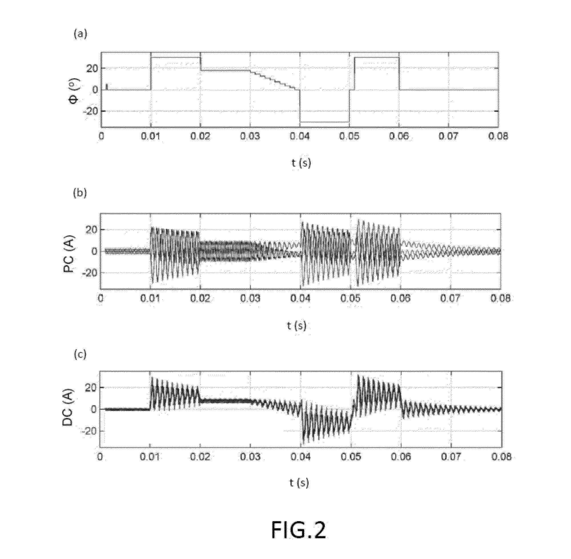
If the transferred power is to be changed abruptly, undesired oscillations as well as an unbalanced distribution of the currents in the phases occur.
The slow change of the phase angle, however, leads to reduced dynamics of the current regulation, so that only a slow regulation of the current would be possible.
Therefore, when it comes to DAB DC-DC converters that are supposed to have high dynamics, this method of oscillation reduction cannot be employed, thereby resulting in undesired oscillations and an unbalanced distribution of the currents in the phases.

Method used


Image

  • Current control for dc-dc converters
  • Current control for dc-dc converters
  • Current control for dc-dc converters

Examples


Embodiment Construction

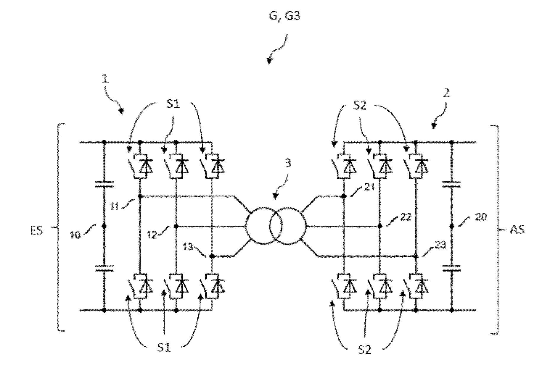
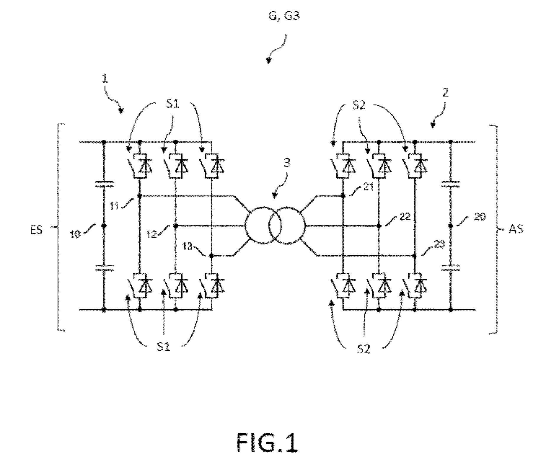
[0043]As an embodiment of the DC-DC converter, FIG. 1 shows a three-phase DC-DC converter G3 with a primary side 1 comprising three actively switched primary voltage bridges 11, 12, 13, each having two active switches Si for converting a DC input voltage ES into primary alternating voltages 111, 112, 113 for each of the primary voltage bridges 11, 12, 13, and with a secondary side 2 comprising three actively switched secondary voltage bridges 21, 22, 23, each having two active switches S2 for converting the secondary alternating voltages 211, 212, 213 into a shared DC output voltage AS for each of the secondary voltage bridges 21, 22, 23. Examples of suitable switches S1, S2 for the voltage bridges are active semiconductor switches (power semiconductors) such, for instance, gate turn-off thyristors, transistors, MOSFETs, IGBTs (insulated gate bipolar transistors) or ICGTs (integrated gate-commuted thyristor) with intelligent gate drivers. In other embodiments, the number of voltage ...


PUM


Abstract

A DC-DC converter having a primary side comprising at least three actively switched primary voltage bridges with several active switches for converting a DC input voltage into primary alternating voltages for each of the primary voltage bridges, and having a secondary side comprising at least three actively switched secondary voltage bridges with several active switches for converting the secondary alternating voltages into a shared DC output voltage for each of the secondary voltage bridges. The primary and secondary alternating voltages are each shifted by a phase angle φ with the periods T, and each of the primary and secondary voltage bridges is coupled to an appertaining phase via one or more transformers.

Description

TECHNICAL FIELD OF THE INVENTION[0001]The invention relates to DC-DC converters having a so-called dual active bridge (DAB) topology as well as to a method for operating these DC-DC converters.STATE OF THE ART[0002]A DC-DC converter, also known as a power converter, refers to an electric circuit that converts a direct current fed in at the input into a direct current having a higher, lower or inverted voltage level. DC-DC converters can be found, for example, in the switched-mode power supply units of PC power supply packs, notebooks, mobile phones, small motors and HiFi devices. Their advantages in comparison to linear power supply units are their better efficiency and lower heat generation. In a linear voltage regulator or in a series resistor, in contrast, the superfluous voltage simply “burns out”.[0003]DC-DC converters are also available as completely encapsulated converter modules that are sometimes intended for direct insertion into printed circuit boards. The output voltage ...

Claims


Application Information

Patent Timeline
IPC IPC(8): H02M3/335
CPCH02M3/33507H02M3/33584H02M1/14H02M1/44
Inventor ENGEL, STEFANDE DONCKER, IR RIK W.A.A.
Owner FLEXIBLE ELEKTRISCHE NETZE FEN GMBH
Learn More