
Method and system for spectral computed tomography (CT) with inner ring geometry

a computed tomography and inner ring technology, applied in tomography, applications, instruments, etc., can solve the problems of affecting the precision of reconstructed spectral images, affecting the performance and high cost of photon counting detectors

Inactive Publication Date: 2015-05-28
TOSHIBA MEDICAL SYST CORP
View PDF29 Cites 26 Cited by
  • Summary
  • Abstract
  • Description
  • Claims
  • Application Information

AI Technical Summary

Benefits of technology

The patent text describes a new system for improving the use of photon counting detectors in computed tomography (CT) scanners. The system uses a combination of conventional energy integrating detectors and photon counting detectors in a unique geometry to capture the spectral nature of the X-ray source. The use of spectral CT offers the advantage of better clinical information without the tradeoffs of conventional CT methods. However, previous attempts to implement spectral CT have faced issues such as beam hardening, temporal resolution, noise balance, and inadequate energy separation. The current invention aims to solve these issues and provide a better solution for spectral CT.

Problems solved by technology

All of these prior art attempts for spectral CT involve tradeoffs while trying to solve issues such as beam hardening, temporal resolution, noise balance, and inadequate energy separation.
For example, dual source solutions are good for noise balance and energy separation but are not so good in some clinical applications for correcting beam hardening and improving temporal resolution.
Fast kV-switching has the potential for good beam hardening correction and good temporal resolution although the noise balance might require a tradeoff with temporal resolution and inadequate energy separation might affect the precision of the reconstructed spectral images.
In general, photon counting detectors are costly and have performance constraints under high flux x-rays.
Although at least one experimental spectral CT system has been reported, the costs of high-rate photon counting detectors are prohibitive for a full-scale implementation.

Method used


Image

  • Method and system for spectral computed tomography (CT) with inner ring geometry
  • Method and system for spectral computed tomography (CT) with inner ring geometry
  • Method and system for spectral computed tomography (CT) with inner ring geometry

Examples


Embodiment Construction

)

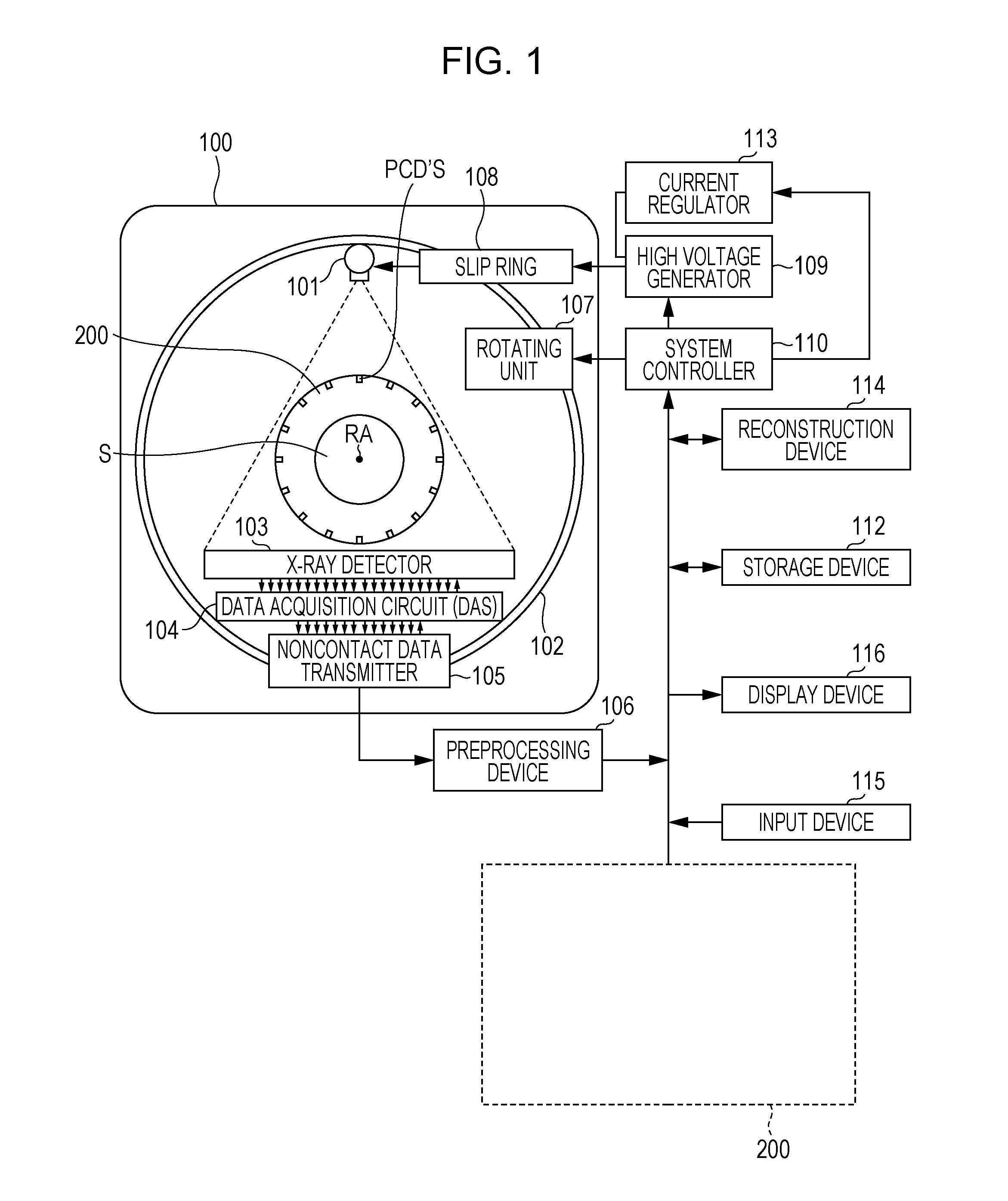
[0018]Referring now to the drawings, wherein like reference numerals designate corresponding structures throughout the views, and referring in particular to FIG. 1, a diagram illustrates one X-ray CT apparatus or scanner according to the current invention including a gantry 100 and other devices or units. The gantry 100 is illustrated from a side view and further includes an X-ray tube 101, an annular frame 102 and a multi-row or two-dimensional array type X-ray detector 103. The X-ray tube 101 and X-ray detector 103 are diametrically mounted across a subject S on the annular frame 102, which is rotatably supported around a rotation axis RA. A rotating unit 107 rotates the frame 102 at a high speed such as 0.4 sec / rotation while the subject S is being moved along the axis RA into or out of the illustrated page.

[0019]The multi-slice X-ray CT apparatus further includes a high voltage generator 109 that generates a tube voltage to be applied to the X-ray tube 101 through a slip ring 1...


PUM


Abstract

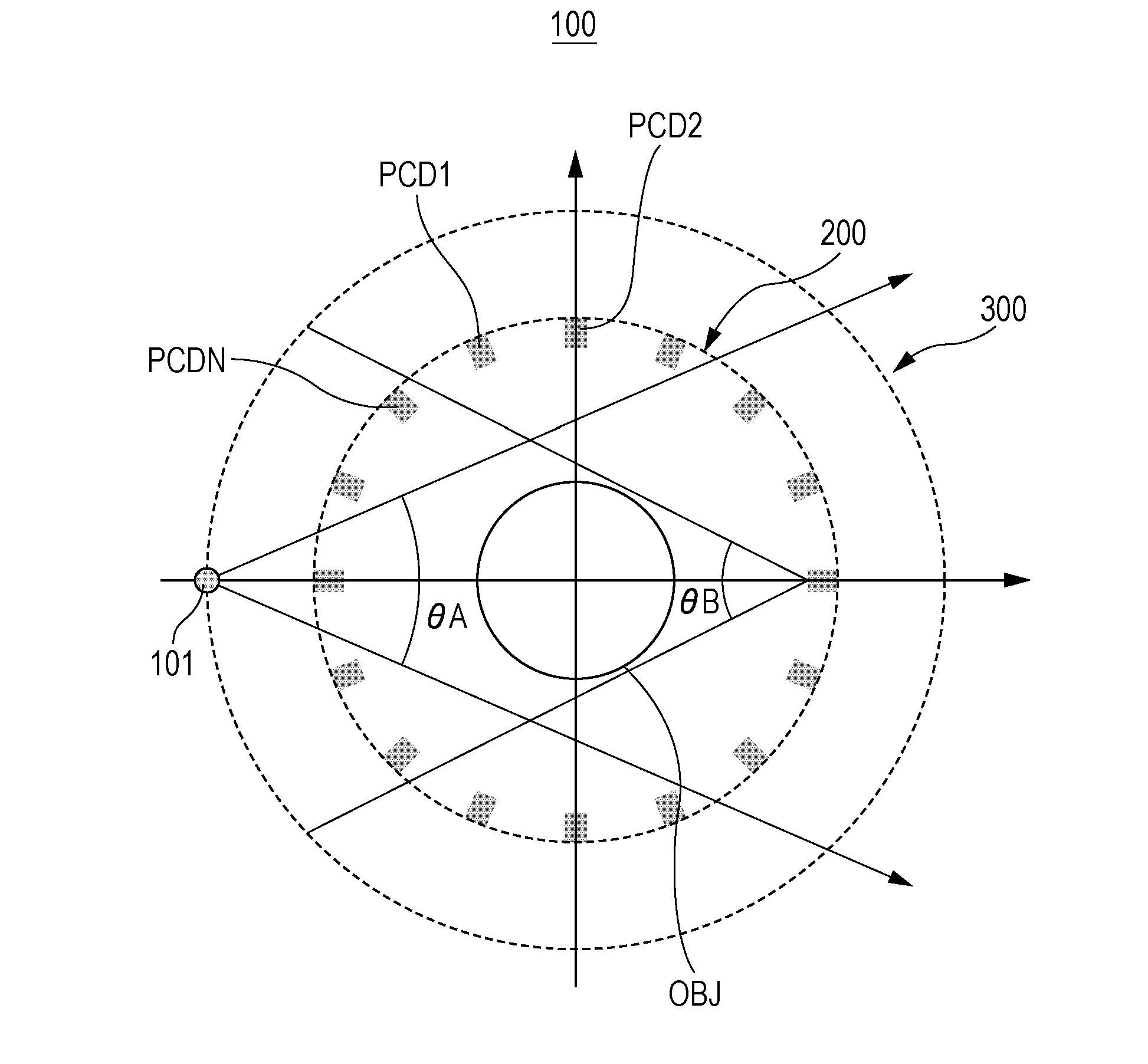
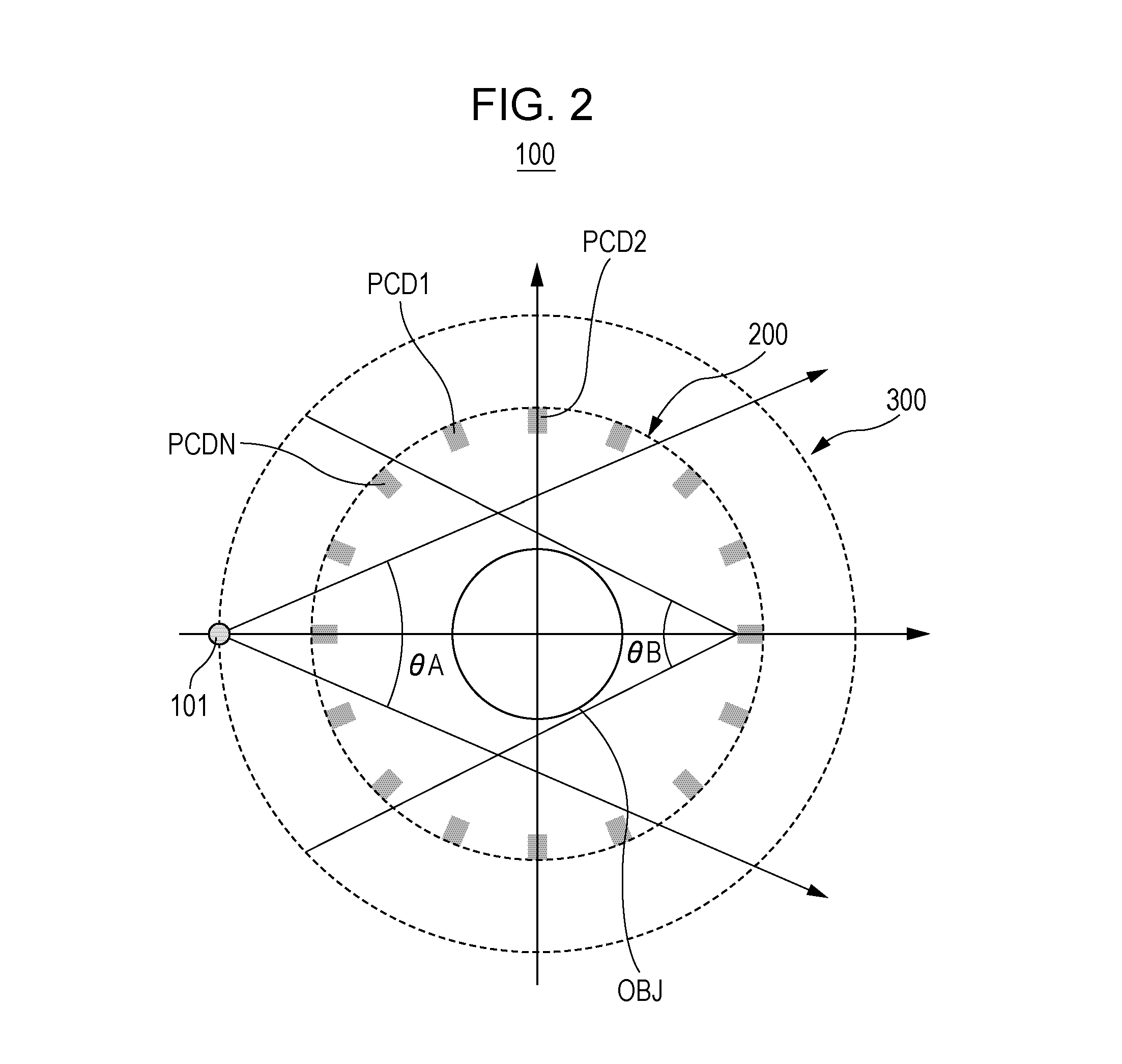
Photon counting detectors are sparsely placed at predetermined positions in the fourth-generation geometry around an object to be scanned in spectral Computer Tomography (CT). An X-ray emitting source rotates radially outside the sparsely placed photon counting detectors. Furthermore, the integrating detectors are placed in the third-generation in combination to the sparsely placed photon counting detectors at predetermined positions in the fourth-generation geometry.

Description

One related patent application Ser. No. 13 / 426,903 has been filed on Mar. 22, 2012 for disclosing a combination of conventional energy integrating detectors and photon counting detectors.FIELD OF THE INVENTION[0001]The current invention is generally related to an image processing and system, and more particularly related to sparse photon counting detectors with an inner ring geometry for spectral Computer Tomography (CT).BACKGROUND OF THE INVENTION[0002]The x-ray beam in most computer tomography (CT) scanners is generally polychromatic. Yet, most of the currently used CT scanners generate images based upon data according to the energy integration nature of the detectors. These conventional detectors are called energy integrating detectors for acquiring energy integration X-ray data. On the other hand, photon counting detectors are configured to acquire the spectral nature of the x-ray source rather than the energy integration nature in acquiring data. To obtain the spectral nature o...

Claims


Application Information

Patent Timeline
IPC IPC(8): A61B6/00A61B6/03
CPCA61B6/4208A61B6/4241A61B6/032A61B6/4007A61B6/4275A61B6/482G01T1/243
Inventor ZAMYATIN, ALEXANDERZOU, YUWANG, XIAOLANWANG, ZHENGYANZHANG, YUEXING
Owner TOSHIBA MEDICAL SYST CORP
Learn More