Adaptable Abrasive Cutting Assembly for Sharpener

a technology of abrasive cutting and abrasive components, which is applied in the field of electric abrasive sharpeners, can solve the problems of reducing the quality of the sharpening edge of the tool, affecting the sharpening effect, and affecting the quality of the sharpening edge, so as to prevent the abrasive assembly from slowing down during the sharpening. , the effect of economic and effective

Active Publication Date: 2015-05-28
SMITHS CONSUMER PROD
View PDF3 Cites 6 Cited by
  • Summary
  • Abstract
  • Description
  • Claims
  • Application Information

AI Technical Summary

Benefits of technology

[0004]Numerous self-powered, electric abrasive sharpeners have been developed in the past. Although some past designs produce satisfactory results, the self-powered systems in the prior art are relatively expensive and must rely on the use of numerous precise components for maintain the abrasive element speed to satisfactorily sharpen tools. One convenient and advantageous feature not found in known sharpeners is to provide an economical and effective technique allowing the abrasive cutting element assembly to adapt to the tools being sharpened. Further, in the past the user of a sharpening would experience run-out or slowing of the abrasive elements, due to tools to be sharpened of different sizes, shapes, and amounts of force applied by the tool. Such run-out will, for example, decrease the quality of the sharpened edge of the tool by producing uneven cutting of the tool edge.
[0005]It is therefore an objective of the invention to provide an improved electric sharpener for knives, scissors, and other implements having a flexible adaptable abrasive assembly for a power sharpener for preventing the abrasive assembly from slowing down during sharpening, the effect of which may produce uneven sharpening results or even stalling of the motor. During sharpening the flexible assembly of the invention absorbs forces applied to the abrasive surface such that a detrimental slowdown of the speed of the sharpener is alleviated. This results in an improved sharpening operation in which there is no significant slowing or altogether stopping of the rotation of the abrasive cutting elements due to their shape, size, or the force applied to the abrasive surface, conditions which previously in the prior art interfered with the quality of sharpening of a tool.

Problems solved by technology

Although some past designs produce satisfactory results, the self-powered systems in the prior art are relatively expensive and must rely on the use of numerous precise components for maintain the abrasive element speed to satisfactorily sharpen tools.
Further, in the past the user of a sharpening would experience run-out or slowing of the abrasive elements, due to tools to be sharpened of different sizes, shapes, and amounts of force applied by the tool.
Such run-out will, for example, decrease the quality of the sharpened edge of the tool by producing uneven cutting of the tool edge.

Method used


Image

  • Adaptable Abrasive Cutting Assembly for Sharpener
  • Adaptable Abrasive Cutting Assembly for Sharpener
  • Adaptable Abrasive Cutting Assembly for Sharpener

Examples


Embodiment Construction

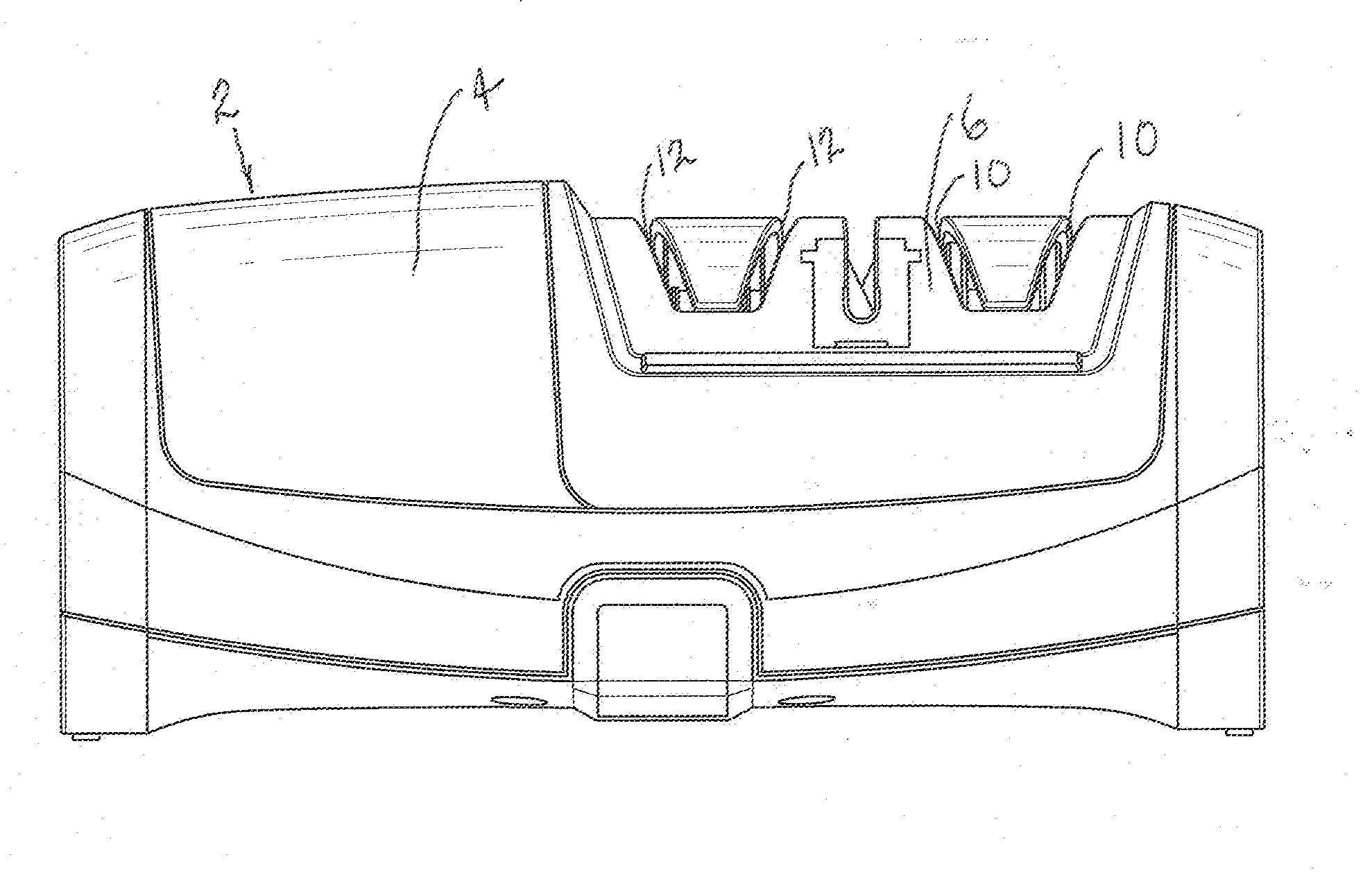
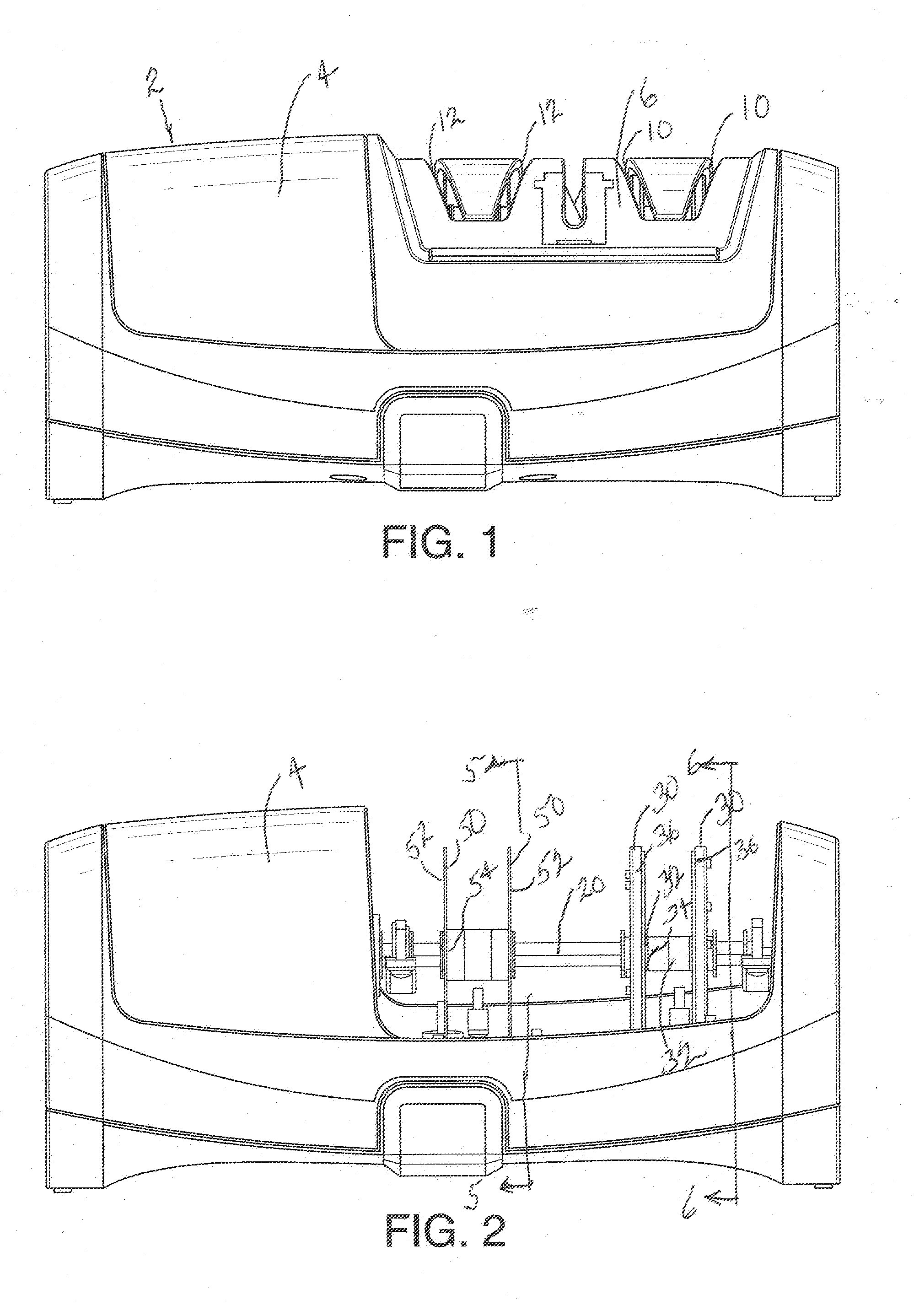
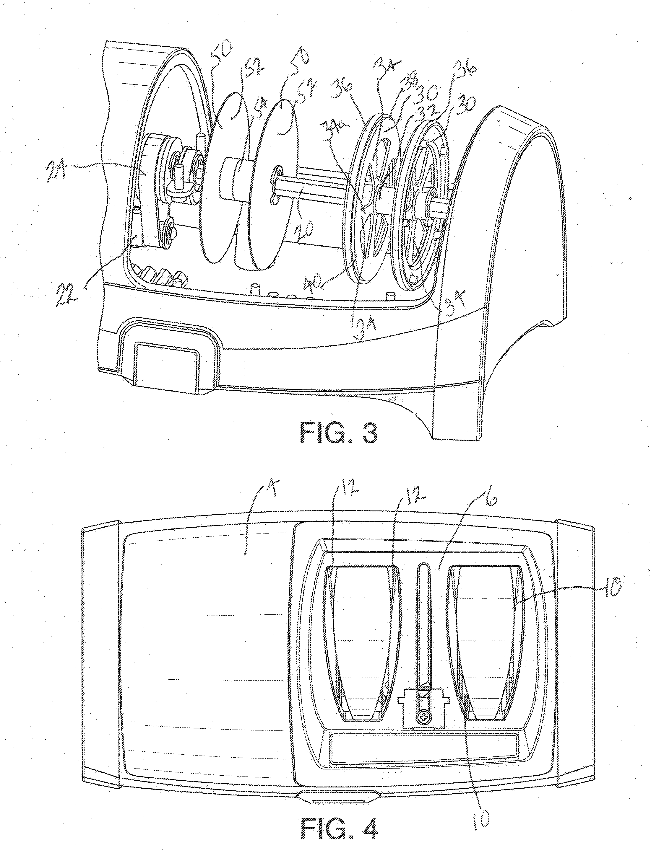
[0012]Referring now to FIGS. 1-6, there is illustrated a self-powered sharpener 2 having a housing 4. A top portion 6 of housing 4 forms a curved enclosure having a first pair of curvilinear slots 10 and a second pair of curvilinear slots 12 which form two respective pairs of adjacent sharpening slots for receiving a variety of implements, such as, for example, knives, scissors, and other tools having edges to be sharpened. As seen in FIGS. 2 and 3, the slots 10 are defined by downward, generally opposed guide surface 10a, 10b integrally formed on housing top portion 6. Similarly the slots 12 are defined by downward, generally opposed guide surface 12a, 12b integrally formed on housing top portion 6. The guide surfaces 10a,b and 12a,b function to properly align the tool being sharpened adjacent abrasive assemblies to be described.

[0013]As best seen in FIGS. 2, 3 and 5, a drive shaft 20 is mounted on suitable bushings within the housing 4 for rotation powered by a conventional electr...


PUM

PropertyMeasurementUnit
flexibleaaaaaaaaaa
rotational speedaaaaaaaaaa
electricaaaaaaaaaa

Abstract

An electric sharpener having a pair of abrasive wheel assemblies including energy absorbing hubs mounted a powered drive shaft and further integral flexible radially extending arms affixed to respective outer abrasive rings. A pair of disk abrasives assemblies are also affixed to the powered rotatable shaft and include a pair of flexible metal disks operatively connected to a hub attached to the rotatable shaft.

Description

BACKGROUND OF THE INVENTION[0001]1. Field of the Invention[0002]This invention relates to abrasive sharpeners, and more particularly, to an electric abrasive sharpener having adaptable flexible abrasive assemblies to prevent slowing abrasive speed and even stall of the motor during sharpening and provide a wide range of cutting capabilities.[0003]2. Summary of the Prior Art[0004]Numerous self-powered, electric abrasive sharpeners have been developed in the past. Although some past designs produce satisfactory results, the self-powered systems in the prior art are relatively expensive and must rely on the use of numerous precise components for maintain the abrasive element speed to satisfactorily sharpen tools. One convenient and advantageous feature not found in known sharpeners is to provide an economical and effective technique allowing the abrasive cutting element assembly to adapt to the tools being sharpened. Further, in the past the user of a sharpening would experience run-ou...

Claims


Application Information

Patent Timeline
Patent Type & Authority Applications(United States)
IPC IPC(8): B24B3/40B24B47/10B24B49/16
CPCB24B3/40B24B47/10B24B49/16B24B3/52B24B3/54
Inventor SMITH, RICHARD S.CHALFANT, LOUIS P.
Owner SMITHS CONSUMER PROD
Why Eureka
Try Eureka