Structurally supporting insert for spinal fusion cage

a cage and structure technology, applied in the field of composite spinal intervertebral body cages, can solve the problems of affecting the stability of the interbody cage, the relative weakness and/or brittleness of the material, and the insertion of the majority of the cages

Active Publication Date: 2015-05-28
HOWMEDICA OSTEONICS CORP
View PDF17 Cites 13 Cited by
  • Summary
  • Abstract
  • Description
  • Claims
  • Application Information

AI Technical Summary

Benefits of technology

[0011]An expandable implant can be configured to expand hydraulically. The body may have a bone graft opening extending through the top member and body, wherein the bone graft port is in fluid communication with the bone graft opening. An expandable implant can also have a torque resistant port formed in the body configured to couple to a tab on an insertion instrument to prevent the body from rotating relative to the insertion instrument. In at least one embodiment, the structural insert can provide a threaded connection with an insertion instrument. The attachment port may have a smooth surface and be concentric with a threaded opening of the structural insert. The body can have an opening into which the structural insert is placed.

Problems solved by technology

Such existing devices for interbody stabilization have important and significant limitations.
One problem with conventional devices for interbody stabilization made of PEEK, other high performance thermoplastics or resorbable polymers is the relative weakness and / or brittleness of these materials compared to the forces required to insert the device between bones of the spinal column.
The failure point for most cages experiencing breakage during insertion is the point of attachment between the intervertebral body cage and the inserter attached to the cage which is used to place the cage between the vertebrae.
Even more challenging can be the rotational moments placed on the implant as it is forced into a rigidly defined space as more than 90 inch-pounds of torque have been recorded during insertion.

Method used


Image

  • Structurally supporting insert for spinal fusion cage
  • Structurally supporting insert for spinal fusion cage
  • Structurally supporting insert for spinal fusion cage

Examples


Embodiment Construction

[0021]In exemplary embodiments, the present disclosure is directed to a device for providing spinal support for fusion wherein the device contains a structural insert to support the loads placed on the device during insertion.

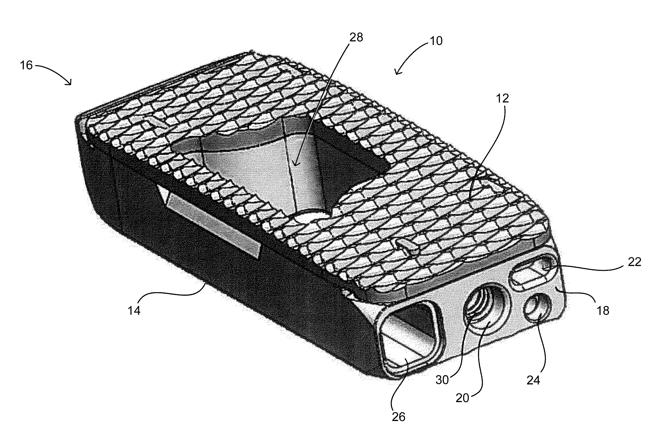
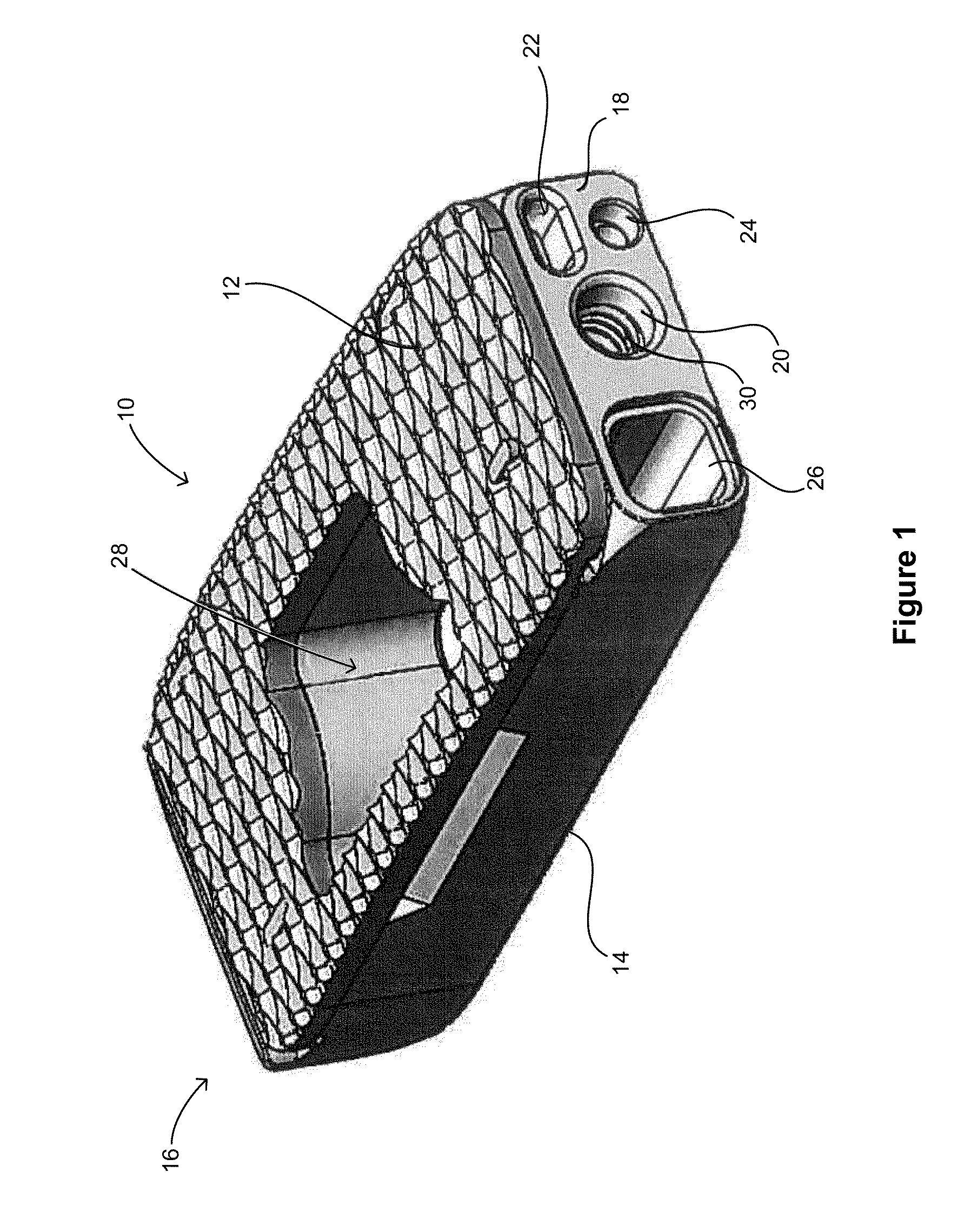
[0022]FIG. 1 shows an embodiment of a spinal fusion cage 10 including a top surface 12, a bottom surface 14, a distal face 16 and a proximal surface 18. The proximal surface 18 is configured to contain an attachment port 20, a torque resistant port 22, a fluid port 24 and a bone graft port 26. The attachment port is used as a means for attaching the spinal fusion cage 10 to an insertion instrument (not shown) for placing the spinal fusion cage into the prepared intervertebral space.

[0023]In this exemplary embodiment, the attachment port 20 is a circular opening that is in communication with a structural threaded insert 30 (best shown in FIGS. 3 and 4). The structural threaded insert is comprised of a material that is typically stronger that the material of the ...


PUM


Abstract

An expandable implant includes a structural insert to provide a robust connection between an insertion instrument and the expandable implant. The structural insert can be made from a different material than the remainder of the implant to withstand compressive, tensile, shear, and torsional loads which may be present while inserting the implant into a patient. The structural insert may be formed as part of a bottom member of the implant or may be a separate element inserted into the implant body. The structural insert may provide a threaded connection to an insertion instrument. The expandable implant may include a bone graft port in fluid communication with a bone graft opening extending through the implant body.

Description

CROSS-REFERENCE TO RELATED APPLICATIONS[0001]This application claims benefit of U.S. Provisional Patent Application No. 61 / 909,667, filed Nov. 27, 2013, the disclosure of which is incorporated by reference herein.BACKGROUND OF THE INVENTION[0002]The present invention generally relates to medical devices for stabilizing the vertebral motion segment. More particularly, the present invention relates to a composite spinal intervertebral body cage for distraction and fusion.[0003]Certain known spine cages or implants are characterized by a body comprising a hydroxyapetite coated surface provided on the exterior surface for contact with adjacent vertebral segments or endplates. A cage of this type may be inserted posteriorly through the neuroforamen of the distracted spine after a surgeon removes disc, bone, and ligament material to create a pathway.[0004]Such existing devices for interbody stabilization have important and significant limitations. Current devices for interbody stabilizati...

Claims


Application Information

Patent Timeline
Patent Type & Authority Applications(United States)
IPC IPC(8): A61F2/44A61F2/46
CPCA61F2/447A61F2/4611A61F2002/4475A61F2310/00023A61F2002/30774A61F2310/00017A61F2002/485A61F2002/30581A61F2002/30579A61F2310/00029A61F2/442A61F2/4601A61F2002/30331A61F2002/30556A61F2002/30601A61F2002/30733A61F2002/30836A61F2002/4629A61F2002/4693A61F2002/30593A61F2/484A61F2002/30042A61F2002/30021
Inventor SICOTTE, MARCELSHULOCK, DAMIEN J.
Owner HOWMEDICA OSTEONICS CORP
Why Eureka
Try Eureka