Compact robotic wrist

a robotic wrist and compact technology, applied in the field of robotic tools and end effectors, can solve the problems of insufficient straight rigid tools

Active Publication Date: 2015-06-04
SRI INTERNATIONAL
View PDF1 Cites 181 Cited by
  • Summary
  • Abstract
  • Description
  • Claims
  • Application Information

AI Technical Summary

Benefits of technology

[0033]In accordance with one aspect, a minimally-invasive surgical tool is provided. The tool comprises a tool shaft, an end effector and a multi-axial wrist disposed between the tool shaft and the end effector, the wrist comprising three or more sets of pulleys arranged in two orthogonal directions. The tool further comprises a drive mechanism comprising four electric motors configured to effect movement of one or both of the wrist and the end effector. Each of the four electric motors is configured to independently control one of four independent cables that wind at least partially around one or more of the three or more sets of pulleys. The motors are configured to vary relative tension between the four independent cables to effect a yaw or pitch motion.
[0034]In accordance with another aspect, a minimally-invasive surgical tool is provided. The tool comprises a tool shaft, an end effector and a multi-axial wrist disposed between the tool shaft and the end effector, the wrist comprising three or more sets of pulleys arranged in two orthogonal directions. The tool further comprises a drive mechanism configured to effect movement of one or both of the wrist and the end effector. The drive mechanism is configured to independently control four independent cables that wind at least partially around one or more of the three or more sets of pulleys to vary relative tension between the four independent cables to effect a yaw or pitch motion.
[0035]In accordance with another aspect, a minimally-invasive surgical tool is provided. The tool comprises a tool shaft, an end effector and a multi-axial wrist disposed between the tool shaft and the end effector, the wrist comprising three or more sets of pulleys arranged in two orthogonal directions. The tool further comprises a drive mechanism comprising three electric motors configured to effect movement of one or both of the wrist and the end effector. The drive mechanism is configured to independently control two cable loops that wind at least partially around one or more of the three or more sets of pulleys to vary relative tension between the two cable loops and between two ends of each cable loop to effect a yaw or pitch motion. One of the three motors is coupled to a mechanism configured to tension two sides of the same cable loop to effect a pitch motion.
[0036]In accordance with another aspect, a minimally-invasive surgical tool is provided. The tool comprises a tool shaft, an end effector and a multi-axial wrist disposed between the tool shaft and the end effector, the wrist comprising three or more sets of pulleys arranged in two orthogonal directions. The tool further comprises means for effecting movement of one or both of the wrist and the end effector via independent control of four independent cables that wind at least partially around one or more of the three or more sets of pulleys to vary relative tension between the four independent cables to effect a yaw or pitch motion.

Problems solved by technology

Straight rigid tools are insufficient in some surgical settings, for example when an organ or anatomical structure is between the incision point or port (e.g., the location the tool enters into the body) and the tissue to be operated upon, because the straight shaft is unable to reach around the organ or anatomical structure to access the tissue.
Another deficiency of straight rigid tools is that they are not well suited for use in what is referred to as single port surgery, where more than one tool is introduced through a single surgical incision or port, which is sometimes desirable to limit trauma to the patient.
To interact cooperatively, the tools need to converge on the operative space from different angles, which straight rigid tools are not well suited for.
With respect to flexible tools, such as curved or bent tools, these tools overcome some of the access and maneuverability issues of straight rigid tools discussed above, but also have deficiencies.
One shortcoming of flexible tools is that they typically are not rigid enough to resist bending loads during surgical procedures.
These flexible tools also have shortcomings, such as being unable to achieve sufficient rigidity to withstand bending loads once bent during a surgical procedure.
Each cable can be arranged such that the relative tension between the two sides of each cable may result in a yaw motion.

Method used


Image

  • Compact robotic wrist
  • Compact robotic wrist
  • Compact robotic wrist

Examples


Embodiment Construction

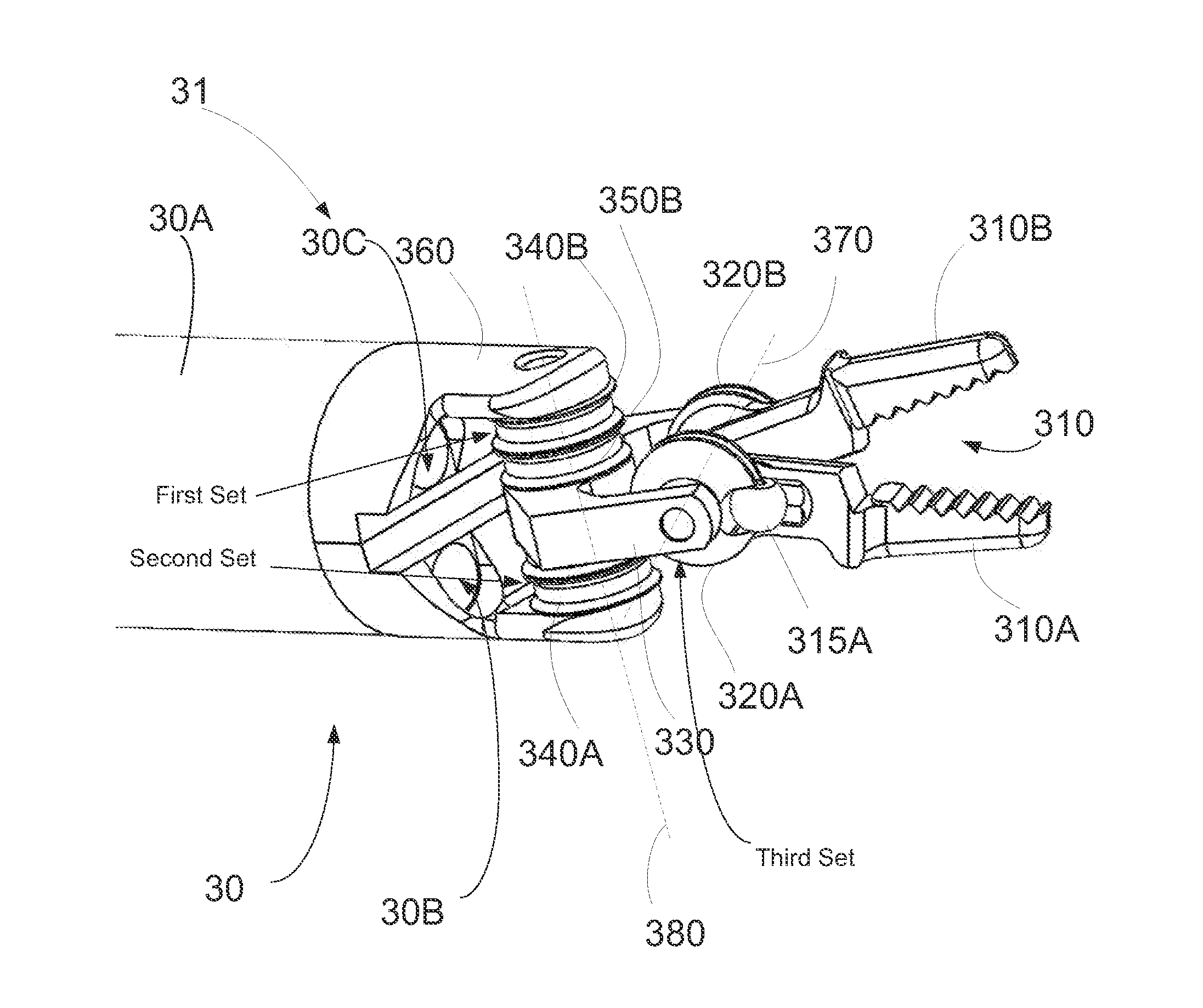
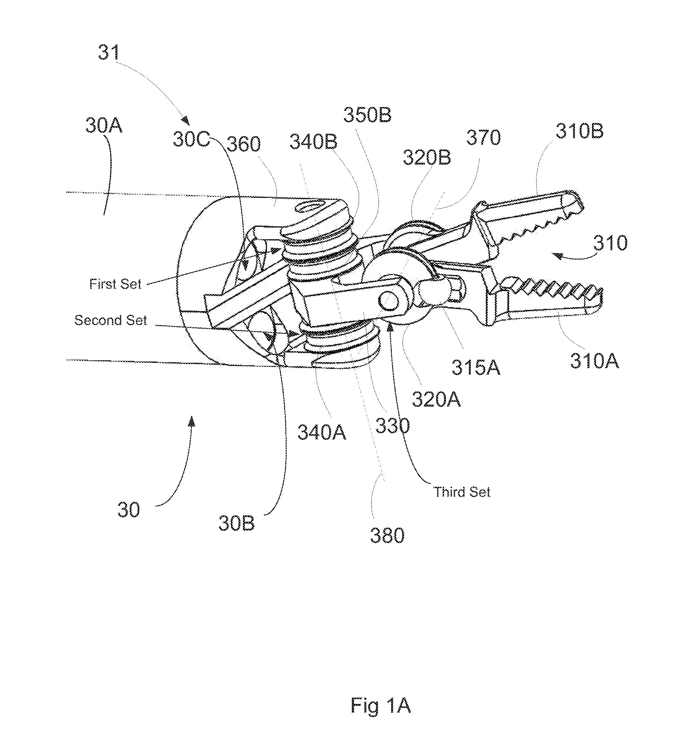
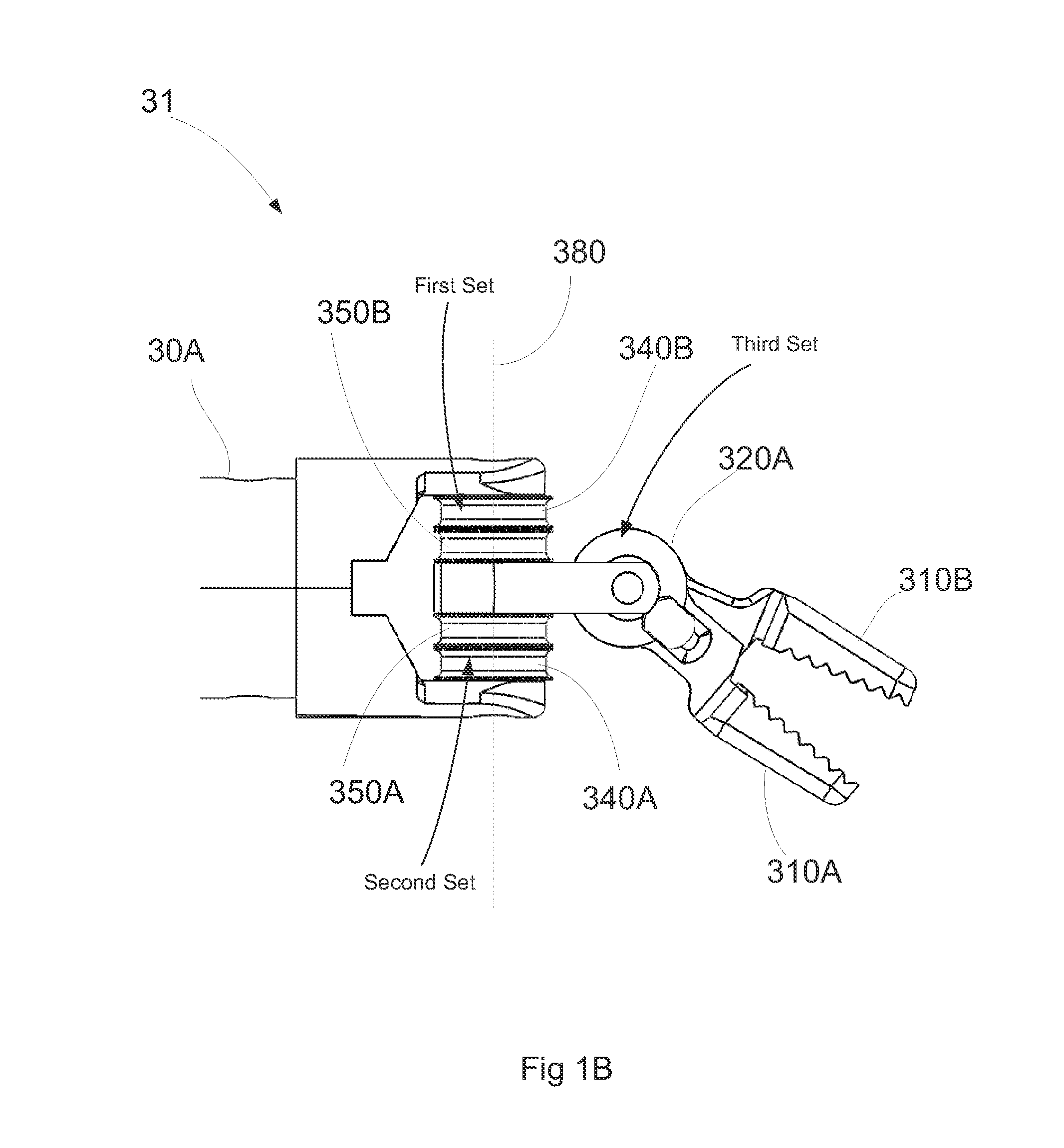
[0088]Described below are embodiments of tools, such as surgical tools, that have various advantages over on-market tools. At least some of the embodiments of tools described herein advantageously provide for less occlusion of the worksite, thereby allowing the operator improved visualization of the worksite. At least some of the embodiments of tools described herein provide for enhanced ability (e.g., of an operator of the tool, of a surgeon operating a tool) to perform complex operations by, for example, reducing the diameter of the wrist of the tool. At least some embodiments of tools describe herein provide enhanced ability to work in areas where access is limited (e.g., a smaller workspace), which can be made possible at least in part by a reduction in the diameter of the wrist of the tool.

[0089]In some embodiments disclosed below, a tool can include an end effector coupled to a tool shaft via a wrist, where the wrist allows for multi-axial motion (e.g., movement in pitch and y...


PUM


Abstract

A surgical tool includes a tool shaft, and end effector and a wrist that couples the end effector to the tool shaft. The tool includes a drive mechanism configured to effect movement of one or both of the wrist and the end effector in yaw and pitch via independent actuation of four independent cable ends of two or more independent cables that extend between the drive mechanism and the wrist.

Description

INCORPORATION BY REFERENCE TO ANY PRIORITY APPLICATIONS[0001]This application claims the priority benefit under 35 U.S.C. §119(e) of U.S. Provisional Application No. 61 / 781,092 filed Mar. 14, 2013, and U.S. Provisional Application No. 61 / 791,248 filed Mar. 15, 2013, all of which are hereby incorporated by reference in their entirety and should be considered a part of this specification.BACKGROUND[0002]1. Field[0003]Robotic end effectors allow robots to manipulate objects. The present application relates to robotic tools, end effectors of the tools, and methods of operating the same.[0004]2. Description of the Related Art[0005]Robots are used for various purposes including industrial, research, medical and non-medical purposes. Each different type of robot may have its own set of unique features and characteristics in addition to features and characteristics that are common among most robots. One common characteristic of most robots is the use of tools. Tools controlled by robots are...

Claims


Application Information

Patent Timeline
Patent Type & Authority Applications(United States)
IPC IPC(8): A61B19/00A61B17/29
CPCA61B19/2203A61B17/29A61B2017/2938A61B2019/2242A61B2019/2246A61B2019/2238A61B2034/715A61B34/71A61B34/30A61B2034/305A61B2034/306Y10S901/29Y10S901/36Y10S901/38B25J15/0028B25J15/0286B25J17/02
Inventor KILROY, PABLO EDUARDO GARCIAMILLER, KENNETH C.EGAN, THOMAS D.LOW, THOMAS P.CRITTENDEN, ARTHUR MAXWELLKOENIG, KAREN SHAKESPEAR
Owner SRI INTERNATIONAL
Why Eureka
Try Eureka