
Electromagnetic stirring device

a stirring device and electromagnetic technology, applied in the direction of mixing devices, casting safety devices, transportation and packaging, etc., can solve the problems of affecting the effect of the stirring device in the cooling chamber, so as to achieve the effect of less results and faster fitting out of the casting machin

Active Publication Date: 2015-06-04
ERGOLINES LAB
View PDF0 Cites 6 Cited by
  • Summary
  • Abstract
  • Description
  • Claims
  • Application Information

AI Technical Summary

Benefits of technology

The present invention provides a solution for a casting machine that improves the quality of the products made by the machine. It also provides better protection for the stirrer in case of emergency situations. Additionally, it allows for faster fitting-out of the machine based on the metal alloy and size of the bar being produced, which improves efficiency and economics.

Problems solved by technology

Since its effect on the still melted nucleus depends strongly on the solidifying phase in which the metallic bar is found at the installation zone of the stirrer itself, it isn't possible keeping into account variations of the solidifying conditions that may happen for example due to variations in the casting temperatures of the melted metallic material in the die or mould, to the extraction speed of the bar in the formation process, to the section shrinkage along the casting line, to the composition of the metallic material, etc.
Consequently in the prior art techniques the effectiveness of the stirrers applied in the cooling chamber is often compromised because the positioning of the stirrer along the bar in the formation process is the result of a compromise that does not keep into account the real conditions that may occur during the casting phase and that can change continuously.
Furthermore during the casting phase different drawbacks may occur that can damage gravely and irreparably the stirrers applied in the cooling chamber.
Consequently the melted metallic material nucleus exits from the bar in the formation process and outflows within the casting chamber with the consequence that it may run over the stirrer and definitively compromise its functionality for prolonged time periods.
Further problems are liable to occur in case of interruption of the electrical energy feeding for the casting machine functioning.
In this case the cooling devices of the stirrer interrupt the cooling liquid flow leaving the stirrer exposed to the heat coming from the metallic bar that remains blocked in the passage duct inside the stirrer with the risk of serious damages to the stirrer internal windings.
Furthermore the prior art techniques providing the presence of stirring devices within the casting chamber have problems from the point of view of the casting machine set-up times because their position should be modified according to the process parameters, e.g. according to the metal alloy that is cast, to the shape in section of the bar that is produced and to the size in section of the bar itself.
However it is not always possible to ensure the correct positioning of the stirrers in correspondence with the estimated optimal point for the action of the stirrer and sometimes the optimal positioning of the stirrer must be wasted to increase the machine fitting-out times, involving, therefore, not-optimal results.
Furthermore the movement of the stirrers during the casting process is not possible because of the presence of the support mechanisms of the casting machine that would prevent their sliding because of the interference problems between the body of the stirrer and the same mechanisms.

Method used


Image

  • Electromagnetic stirring device
  • Electromagnetic stirring device
  • Electromagnetic stirring device

Examples


example 1

[0075]The temperature (FIG. 17) and solidifying profiles (FIG. 18) are estimated starting from the casting parameters relative to the casting of a C40 type steel that is poured within a square mould with side of 160 mm with the following parameters:

[0076]Mould section: 160×160 mm . . . Steel type: C40

[0077]Casting speed: 2.00 m / min . . . Steel range: 401.92 kg / min

[0078]Metallurgic length: 14.90 m . . . Temperature in tundish: 1522° C.

[0079]Liquidus temperature: 1492° C. Solidus temperature: 1439° C.

[0080]Cooling of first zone of the secondary cooling part with 65 l / min on 0.6 metres range

[0081]Cooling of second zone of the secondary cooling part with 110 l / min on 2.0 metres range

[0082]Cooling of the third zone of the secondary cooling part with 58 l / min on 5.0 metres range

[0083]On the solidifying profile (FIG. 18) the shell thickness is selected corresponding to a first position of application of one first of the electromagnetic stirring devices (1), for example in correspondence wi...

example 2

[0084]On the basis of the data reported for the example 1, on the solidifying profile (FIG. 18) the shell thickness is selected corresponding to a second application position of a second one of the electromagnetic stirring devices (1), for example in correspondence with a shell thickness equal to 75%. It is obtained a second zone (Z2) that constitutes the optimal positioning zone of the second electromagnetic stirring device (1). This second zone (Z2) is identified as the zone comprised between a first value in abscissa that corresponds to the point of intersection between the horizontal straight line corresponding to the shell thickness of 75% and the solid fraction line equal to 0.05 and a second value in abscissa that corresponds to the point of intersection between the horizontal straight line corresponding to the shell thickness of 75% and the solid fraction line equal to 0.2. In the example represented the second zone (Z2) is approximately comprised between the points having a...

example 3

[0085]On the basis of the example 2, the influence on the optimal positioning of the second electromagnetic stirring device (1) has been valued according to the type of steel and casting rate, estimating the corresponding solidifying sections and obtaining the results reported in the following in Table 1.

TABLE 1SQUARE SECTION 160Casting speedOptimal position d2Steel type[m / min]Distance from meniscus [m]35KB1.810.32.011.6C401.810.02.011.416MnCr51.810.62.012.1


PUM

PropertyMeasurementUnit
thicknessaaaaaaaaaa
frequencyaaaaaaaaaa
frequencyaaaaaaaaaa

Abstract

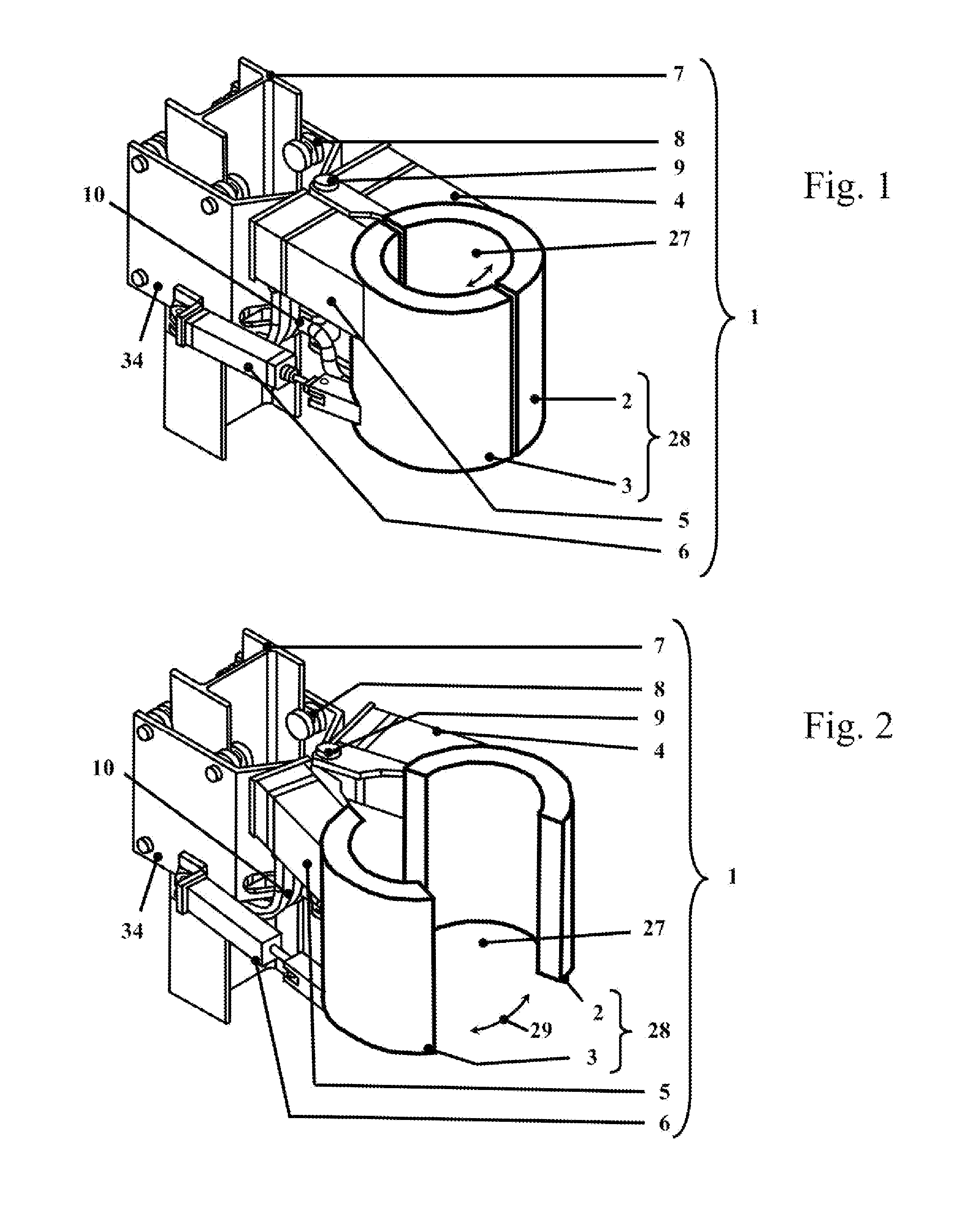
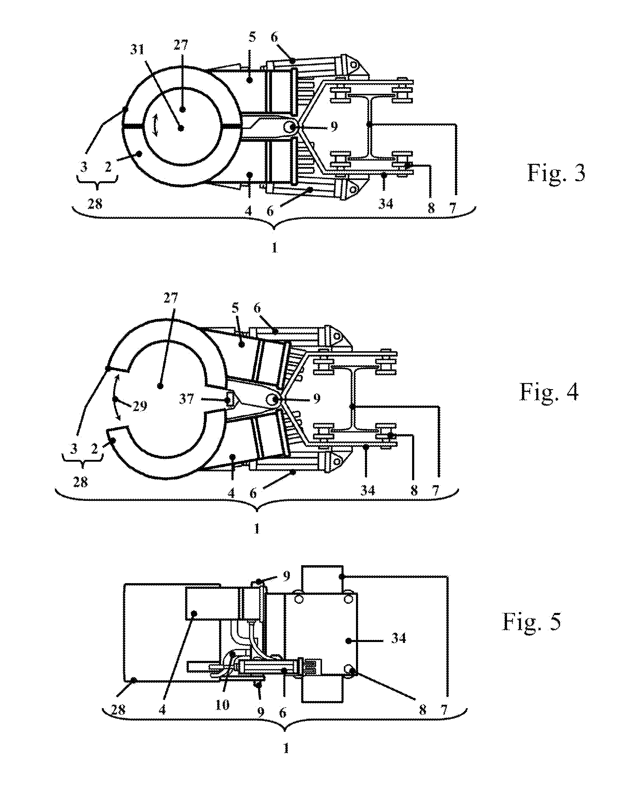
An electromagnetic stirring device of melted metallic materials inside a cooling chamber of a casting machine having a retaining body of induction coils that is a body composed of at least two reciprocally different portions.

Description

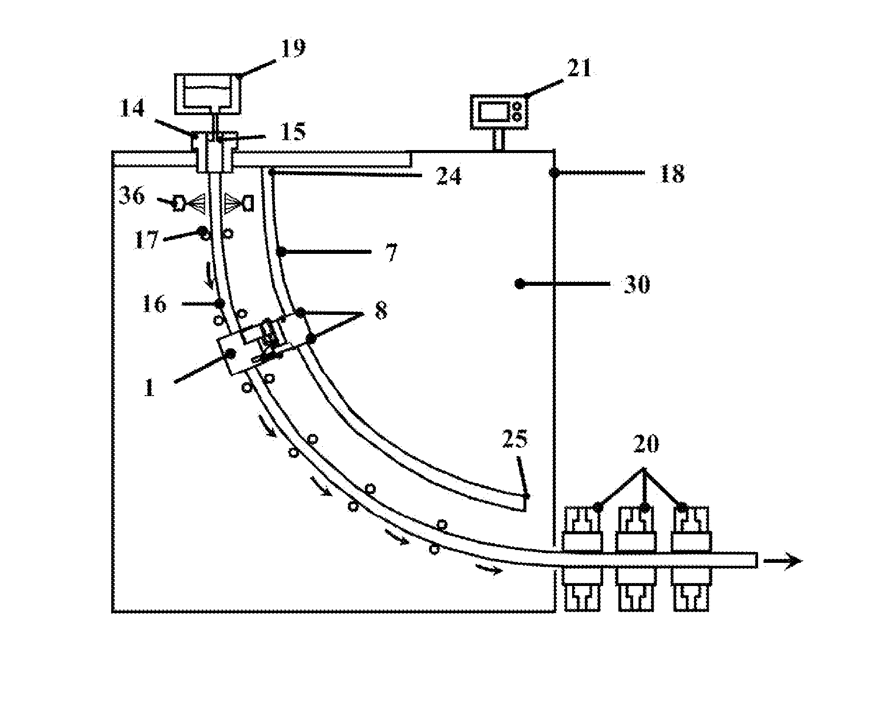
CROSS-REFERENCE TO RELATED U.S. APPLICATIONS[0001]Not applicable.STATEMENT REGARDING FEDERALLY SPONSORED RESEARCH OR DEVELOPMENT[0002]Not applicable.NAMES OF PARTIES TO A JOINT RESEARCH AGREEMENT[0003]Not applicable.REFERENCE TO AN APPENDIX SUBMITTED ON COMPACT DISC[0004]Not applicable.BACKGROUND OF THE INVENTION[0005]1. Field of the Invention[0006]The present invention relates to an electromagnetic stirring device (1) of melted metallic material inside a cooling chamber (30) of a casting machine (18) according to the characteristics of the pre-characterizing part of claim1.[0007]This invention relates also to a casting machine (18) according to the characteristics of the pre-characterizing part of claim 17.[0008]The present invention also relates to a casting process for the production of metallic material bars (16) according to the characteristics of the pre-characterizing part of claim 20.DEFINITIONS[0009]Herein description and in the appended claims the following terms must be i...

Claims


Application Information

Patent Timeline
Patent Type & Authority Applications(United States)
IPC IPC(8): B22D11/12B22D11/124B01F13/08
CPCB22D11/122B01F2215/0044B22D11/124B01F13/08B22D11/115B22D11/12B01F33/45B01F2101/26
Inventor DE MONTE, STEFANOSPAGNUL, STEFANO
Owner ERGOLINES LAB
Learn More