Powertrain control system and method

a powertrain and control system technology, applied in the direction of braking systems, position/direction control, driver input parameters, etc., can solve problems such as affecting the stability of motor vehicles, and achieve the effect of higher integrity rating and integrity rating

a powertrain and control system technology, applied in the direction of braking systems, position/direction control, driver input parameters, etc., can solve problems such as affecting the stability of motor vehicles, and achieve the effect of higher integrity rating and integrity rating

US20150151737A1Active Publication Date: 2015-06-04JAGUAR LAND ROVER LTD

Image

  • Powertrain control system and method
  • Powertrain control system and method
  • Powertrain control system and method

Examples


Embodiment Construction

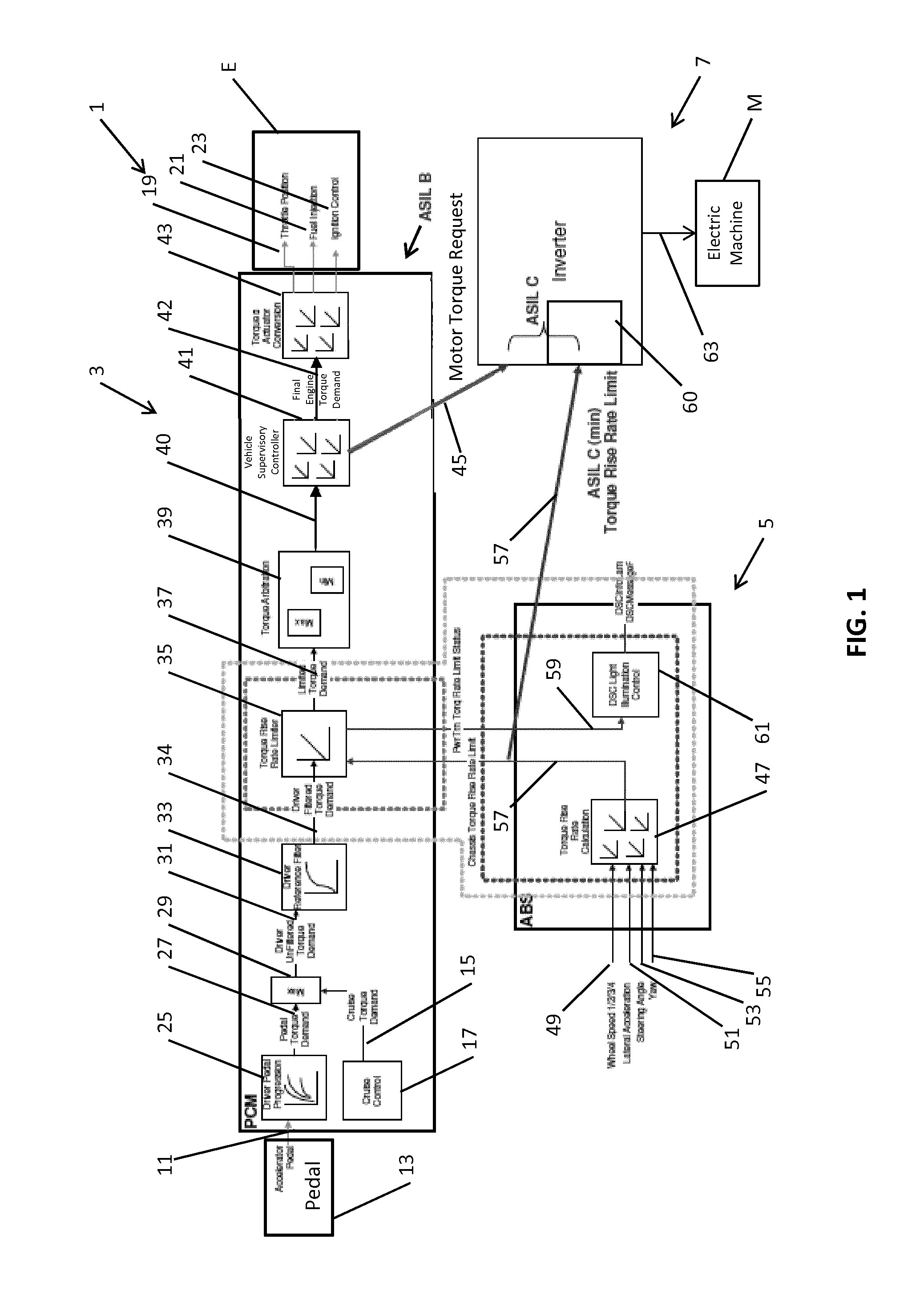
[0036]A powertrain control system 1 in accordance with an embodiment of the present invention is illustrated in FIG. 1. The powertrain control system 1 is configured to control an internal combustion engine E and an electric drive motor M of a hybrid motor vehicle (not shown) having four driven wheels (not shown). The present invention could also be used for vehicles having two driven wheels.

[0037]The powertrain control system 1 comprises a powertrain control module (PCM) 3, an anti-lock brake system (ABS) module 5 and an inverter 7. The powertrain control module 3 outputs engine control signals to the internal combustion engine E. The powertrain control module 3 also outputs motor control signals to the inverter 7 to control the electric drive motor M.

[0038]In the present embodiment, the electric drive motor M is coupled to a transmission of the vehicle, but other configurations can be implemented, for example providing an electric drive motor in a hub of a driven wheel of the vehi...


PUM


Abstract

The present invention relates to a powertrain control system (1) for a vehicle. The powertrain control system (1) includes a torque limit calculator (47) for generating a torque control signal based (57) on one or more vehicle operating parameters. A torque request module (43) is provided for generating a torque request signal (45) and a torque control module (7) controls the torque applied by the powertrain. The torque control module (7) is configured to receive the torque request signal (45) from the torque request module (43) and the torque control signal (57) from the torque limit calculator (47) and to control the torque applied by the powertrain in dependence on the torque request signal (45) and the torque control signal (57). The present invention also relates to a control system; and a method of operating a powertrain control system.

Description

TECHNICAL FIELD[0001]The present invention relates to a powertrain control system and method. The powertrain control system can, for example, be implemented in a motor vehicle. Aspects of the present invention relate to a control system and a method of operating a powertrain.BACKGROUND OF THE INVENTION[0002]The unintentional application of torque (either positive or negative, i.e. torque leading to acceleration or deceleration of the vehicle) could potentially affect the stability of a motor vehicle. This is particularly relevant for vehicles incorporating electric drive motors (or electric machines) which can implement a higher rate of change in the applied torque than internal combustion engines (for example, due to the speed of application of the electric field and lower rotational inertia). Accordingly, the control of an electric drive motor, when applying both positive (drive) torque and negative (braking) torque, is of the utmost importance.[0003]The present invention sets out...

Claims


Application Information

Patent Timeline
04 Jun 2015
Publication
US20150151737A1
IPC
B60W20/00; B60W50/08; B60W30/02; B60W30/18; B60W10/06; B60W10/08; B60L50/16
CPC
B60W20/108; B60W10/06; B60W10/08; Y10S903/93; B60W30/18172; B60W50/087; B60W2050/0012; B60W30/02
Inventors
BIRCH, JOHN; DARNELL, PAUL