Modular conveyor system and corresponding method

a conveyor system and module technology, applied in the field of module-based conveyancing or conveying systems, can solve the problems of inability to dynamically adapt the controlling of each control device, inability to provide for a simple way of making available information on the entire section, and inability to achieve optimal decentralization of control. , to achieve the effect of facilitating the migration of modules

Active Publication Date: 2015-06-04
SAVOYE
View PDF3 Cites 22 Cited by
  • Summary
  • Abstract
  • Description
  • Claims
  • Application Information

AI Technical Summary

Benefits of technology

[0058]Thus, each control device is pre-assembled with one or more zones to form a pre-assembled module. Advantageously, the invention uses a limited number of standard, pre-assembled modules (this number depends e

Problems solved by technology

The prior-art solution of modular conveying systems described in detail here above, has several drawbacks, and especially:the decentralizing of the control is not optimal.
But each control device is not capable of dynamically adapting the controlling of its zone.
The two control devices with which it is connected do not send it information enabling such a dynamic adaptation (there is no information on upstream or downstream sub-sections situated on either side of the controlled zone);it does not provide for a simple way of making available information on the entire section (for example the conveyor filling rate).
To an even greater extent, it does not enable such section information to be communicated out of the section, i.e. to one or more other sections or again to a computerized supervision system (for example of the WCS (warehouse control system), WMS (warehouse management system), control screens, etc) types;it does not enable the transit, at the same time as the loads are transported from one end to the other of the section, of the tracking information as

Method used


Image

  • Modular conveyor system and corresponding method
  • Modular conveyor system and corresponding method
  • Modular conveyor system and corresponding method

Examples


Embodiment Construction

[0076]In all the figures of the present document, the identical elements and steps are designated by a same numerical reference.

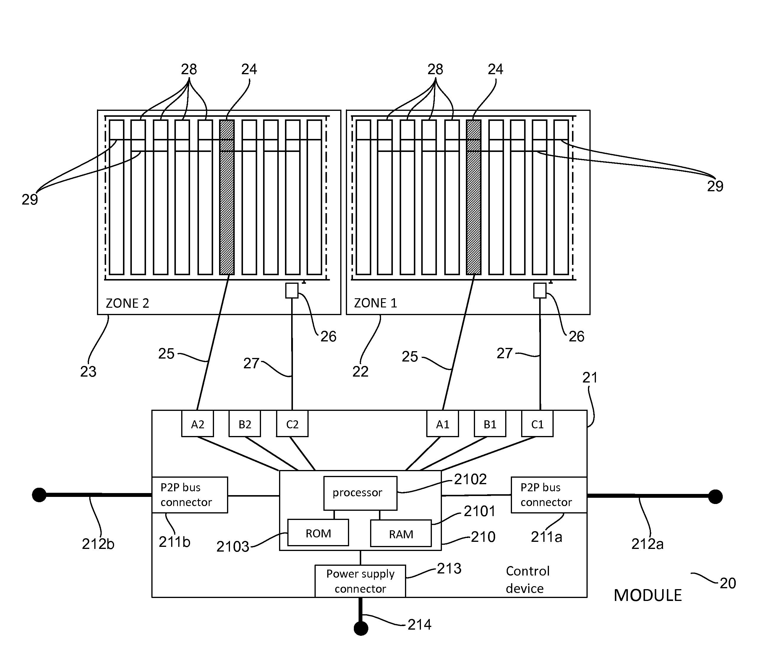
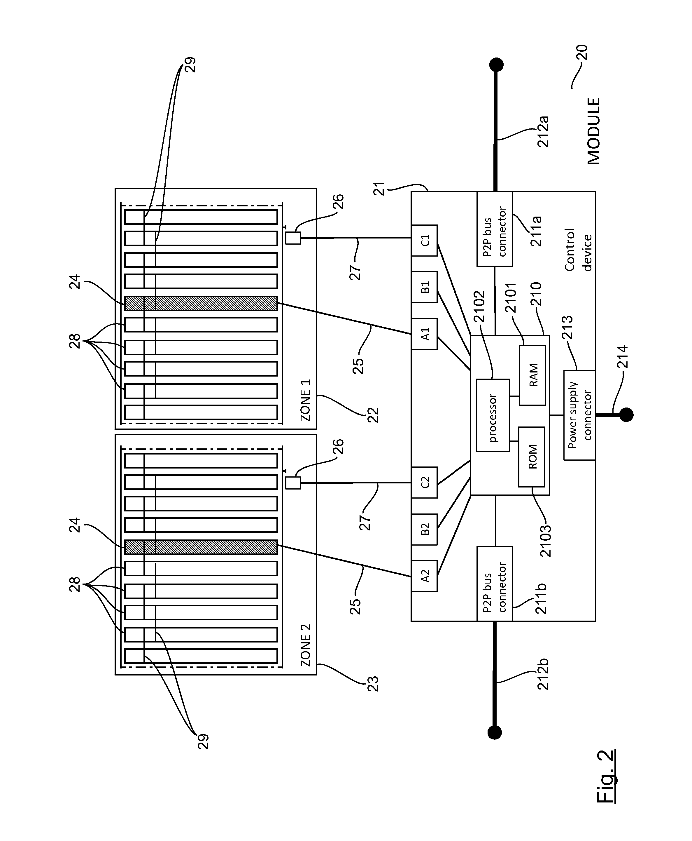
[0077]Referring now to FIG. 2, we present a module 20 according to one particular embodiment of the invention.

[0078]The module 20 is a double module comprising a control device 21 and two zones 22, 23 (also denoted as “zone 1” and “zone 2”) associated with and controlled by the control device 21.

[0079]Each zone 22, 23 comprises:[0080]a drive roller (actuator) 24 receiving, through a link 25, a command signal coming from the control device 21;[0081]slave rollers 28, driven in cascade by the drive roller 24 via transmission belts 29; and[0082]a sensor 26 sending, via a link 27, a presence signal 27 towards the control device 21.

[0083]In variants, each zone can include several actuators (instead of only one) and one or more sensors (instead of only one).

[0084]The control device 21 comprises:[0085]a control unit 210 (see detailed description here below);[0086]t...


PUM


Abstract

A conveyor system includes successive modules forming a conveyor segment, each module includes a control device associated with, and controlling, at least one zone. Each control device includes a communication device for communicating with the control devices included in the adjacent modules. The control devices execute a mechanism for propagation and enrichment of quantitative segment information, from the two end zones of the conveyor segment, thereby providing for each zone: a first quantitative segment information item (propagated and enriched from upstream to downstream and relating to all of the zones in an upstream sub-segment located upstream from the zone) and/or a second quantitative segment information item (propagated and enriched from downstream to upstream and relating to all of the zones in a downstream sub-segment located downstream from the zone). Each control device dynamically adapts the behaviour of each zone it controls, according to the available quantitative segment information.

Description

1. CROSS-REFERENCE TO RELATED APPLICATIONS[0001]This application is a Section 371 National Stage Application of International Application No. PCT / EP2013 / 062213, filed Jun. 13, 2013, the content of which is incorporated herein by reference in its entirety, and published as WO 2013 / 186288 on Dec. 19, 2013, not in English.2. FIELD OF THE INVENTION[0002]The field of the invention is that of the conveyance or conveying of isolated, heavy or light loads.[0003]More specifically, the invention relates to a modular conveyance or conveying system, i.e. a conveying system comprising a plurality of successive modules, assembled in a determined sequence and forming a conveying section. Each module comprises a control device and at least one zone associated with and controlled (or driven) by the control device. Each control device included in a given module comprises means of communication with the control devices included in the modules placed on either side of the given module in the sequence. ...

Claims


Application Information

Patent Timeline
IPC IPC(8): B65G43/00G05B15/02
CPCG05B15/02B65G43/00B65G43/10
Inventor COLLOT, PATRICK
Owner SAVOYE
Why Eureka
Try Eureka