Low noise compressor rotor for geared turbofan engine

Active Publication Date: 2015-06-04
MTU AERO ENGINES GMBH
View PDF4 Cites 6 Cited by
  • Summary
  • Abstract
  • Description
  • Claims
  • Application Information

AI Technical Summary

Benefits of technology

The patent describes a gas turbine engine with a fan and turbine section. The engine has a gear reduction that reduces the speed of the fan relative to the turbine section. The compressor rotor has a number of blades that rotate at a certain speed. The formula for the speed of the blades is derived from the number of blades and the rotational speed of the compressor rotor. The engine produces a certain amount of thrust and has a specific gear ratio. The bypass ratio is the ratio of the volume of air delivered into the bypass duct compared to the volume of air delivered into the compressor rotor. The engine has a higher pressure turbine rotor and a lower pressure turbine rotor, and the fan drive turbine rotor is the lower pressure turbine rotor. The gear reduction is positioned between the fan and the compressor rotor. The formula for the speed of the blades is derived from the number of blades and the rotational speed of the compressor rotor. The technical effects of the patent include improved efficiency, increased power output, and reduced noise.

Problems solved by technology

The low pressure turbine or compressor can be a significant noise source, as noise is produced by fluid dynamic interaction between the blade rows and the vane rows.
However, acoustically cut-off designs may come at the expense of increased weight and reduced aerodynamic efficiency.

Method used


Image

  • Low noise compressor rotor for geared turbofan engine
  • Low noise compressor rotor for geared turbofan engine

Examples


Embodiment Construction

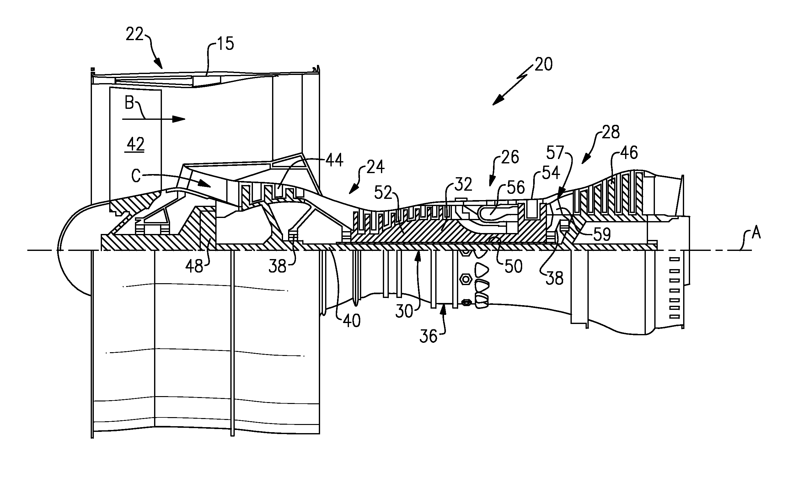
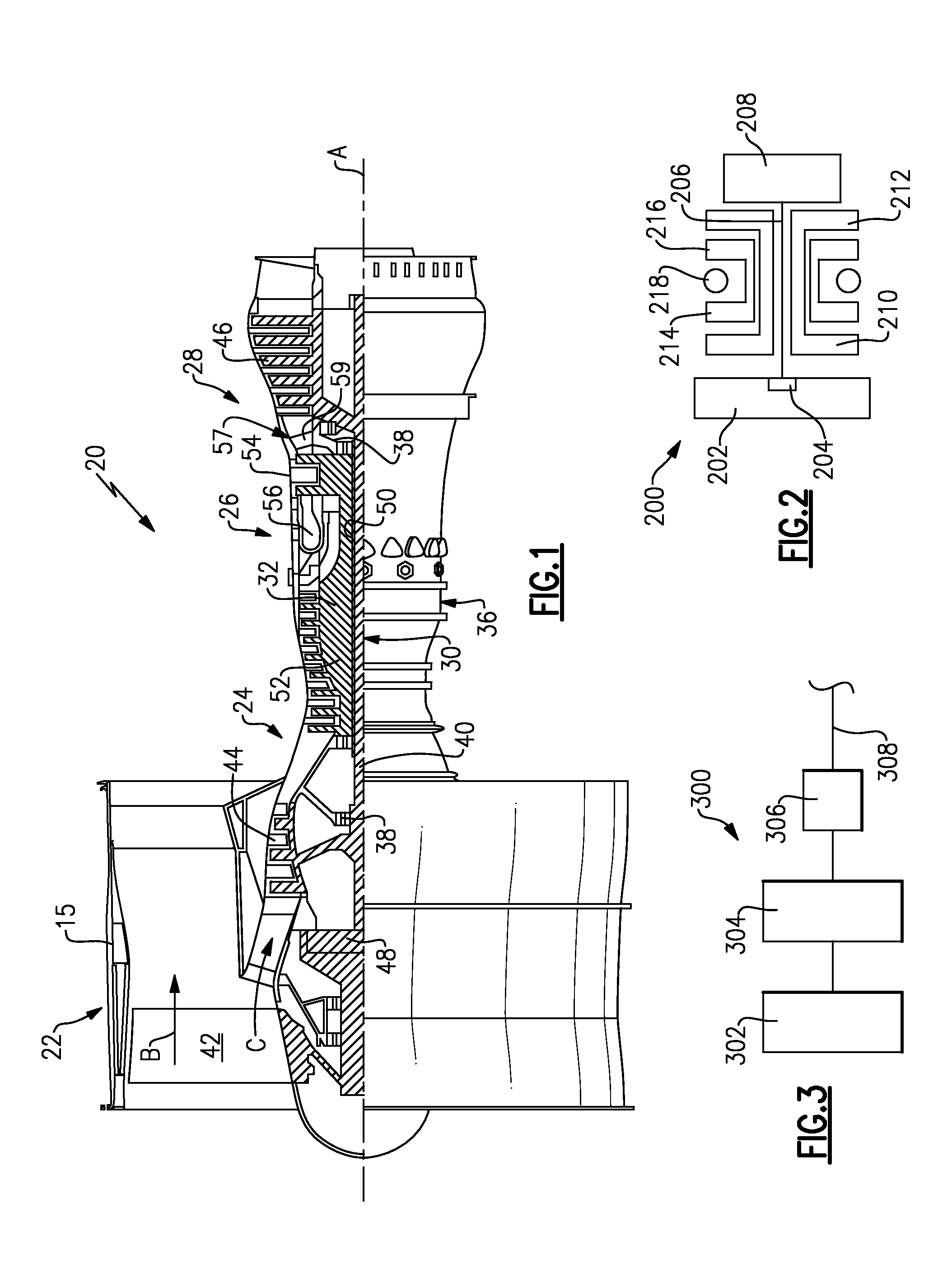
[0039]FIG. 1 schematically illustrates a gas turbine engine 20. The gas turbine engine 20 is disclosed herein as a two-spool turbofan that generally incorporates a fan section 22, a compressor section 24, a combustor section 26 and a turbine section 28. Alternative engines might include an augmentor section (not shown), or an intermediate spool, among other systems or features. The fan section 22 drives air along a bypass flowpath B in a bypass duct defined within a nacelle 15, while the compressor section 24 drives air along a core flowpath C for compression and communication into the combustor section 26 then expansion through the turbine section 28. Although depicted as a turbofan gas turbine engine in the disclosed non-limiting embodiment, it should be understood that the concepts described herein are not limited to use with turbofans as the teachings may be applied to other types of turbine engines including three-spool architectures.

[0040]The engine 20 generally includes a low...


PUM

PropertyMeasurementUnit
Massaaaaaaaaaa
Frequencyaaaaaaaaaa
Pressureaaaaaaaaaa

Abstract

A gas turbine engine has a fan and a turbine having a fan drive turbine rotor. The fan drive turbine rotor drives a compressor rotor. A gear reduction effects a reduction in the speed of the fan relative to an input speed from the fan drive turbine rotor that drives the compressor rotor. The compressor rotor has a number of compressor blades in at least one of a plurality of rows of the compressor rotor. The blades operate at least some of the time at a rotational speed. The number of compressor blades in at least one row and the rotational speed are such that the following formula holds true for at least one row of the compressor rotor turbine: (number of blades×rotational speed) / 60 s≧5500 Hz, and the rotational speed is in revolutions per minute. A method of designing a gas turbine engine and a compressor module are also disclosed.

Description

CROSS-REFERENCE TO RELATED APPLICATION[0001]This application is a continuation-in-part of U.S. patent application Ser. No. 14 / 144,710, filed Dec. 31, 2013, which is a continuation of U.S. patent application Ser. No. 14 / 016,436, filed Sep. 3, 2013, now U.S. Pat. No. 8,714,913, issued May 6, 2014, which is a continuation of U.S. patent application Ser. No. 13 / 630,276, filed Sep. 28, 2012, now U.S. Pat. No. 8,632,301, issued Jan. 21, 2014.BACKGROUND[0002]This application relates to the design of a gas turbine engine rotor which can be operated to produce noise that is less sensitive to human hearing.[0003]Gas turbine engines are known, and typically include a fan delivering air into a compressor. The air is compressed in the compressor and delivered downstream into a combustor section where it was mixed with fuel and ignited. Products of this combustion pass downstream over turbine rotors, driving the turbine rotors to rotate.[0004]Typically, there is a high pressure turbine rotor, and...

Claims


Application Information

Patent Timeline
IPC IPC(8): F02C7/24F02C7/36
CPCF02C7/24F05D2260/96F02C7/36F01D5/02F01D5/12Y10T29/49236Y10T29/4932F05D2220/36F05D2260/40311Y02T50/60
Inventor TOPOL, DAVID A.MORIN, BRUCE L.
Owner MTU AERO ENGINES GMBH
Why Eureka
Try Eureka