Gas turbine combustor diagnostic system and method

a technology of combustor and diagnostic system, which is applied in the direction of lighting and heating equipment, instruments, computer control, etc., can solve the problem of changing one or more operational parameters of one or more combustors

Active Publication Date: 2015-06-04
GENERAL ELECTRIC CO +1
View PDF0 Cites 76 Cited by
  • Summary
  • Abstract
  • Description
  • Claims
  • Application Information

AI Technical Summary

Problems solved by technology

However, variations in the combustion process, such as due to variations in fuel composition, oxidant composition, the nature of other materials present within the combustor, the end use of the gases produced in the combustor, or any combination thereof, may cause one or more operational parameters of one or more of the combustors to change.

Method used


Image

  • Gas turbine combustor diagnostic system and method
  • Gas turbine combustor diagnostic system and method
  • Gas turbine combustor diagnostic system and method

Examples


embodiment 1

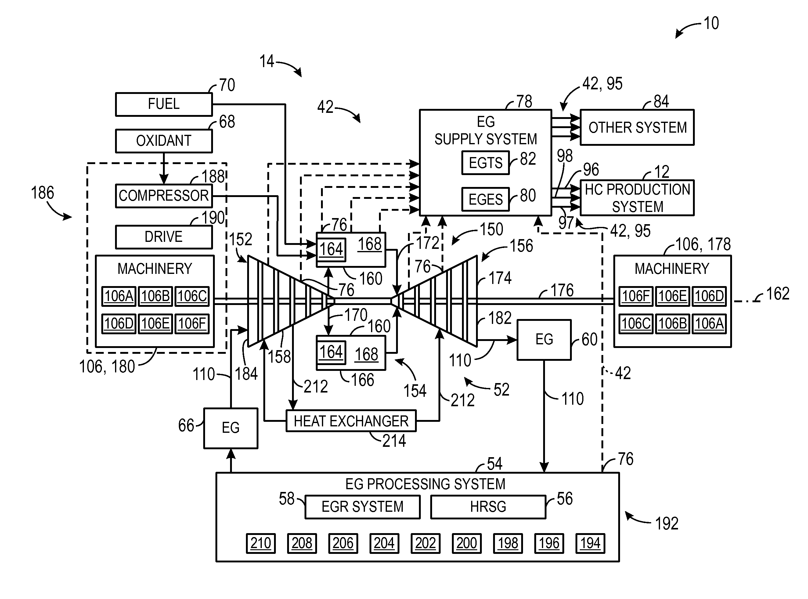
[0151]A system, comprising: a gas turbine system, comprising: a turbine combustion system comprising a plurality of turbine combustors each configured to combust a fuel / oxidant mixture to produce combustion products; a turbine driven by the combustion products produced by the turbine combustion system; a plurality of sensors positioned downstream of the turbine combustion system and configured to monitor one or more parameters of the combustion products; and a control system comprising one or more non-transitory machine-readable media collectively storing one or more sets of instructions executable by a processor to perform a turbine combustion system diagnostic routine comprising: adjusting an operational parameter of a first turbine combustor of the plurality of turbine combustors to cause a change in the combustion products produced by the first turbine combustor; identifying respective sensor responses of one or more first sensors of the plurality of sensors that detects the cha...

embodiment 2

[0152]The system of embodiment 1, wherein the turbine combustion system diagnostic routine comprises comparing the respective sensor responses to an expected sensor response to diagnose the condition, and wherein the control system performs a corrective action, provides a user-perceivable indication, or a combination thereof, if at least one of the respective sensor responses and the expected sensor response are not within a predetermined tolerance of one another.

embodiment 3

[0153]The system of embodiments 1 or 2, wherein adjusting the operational parameter of the first turbine combustor of the plurality of turbine combustors comprises adjusting a fuel / oxidant ratio in the first turbine combustor by adjusting a fuel level trim valve such that the expected sensor response is indicative of a particular fuel / oxidant ratio, wherein when a first sensor response of a single sensor of the one or more first sensors is not within the predetermined tolerance of the particular fuel / oxidant ratio, the control system uses a sensor of the one or more first sensors that is adjacent to the single sensor to monitor the fuel / oxidant ratio, provides a fault indication of the single sensor, or a combination thereof.


PUM


Abstract

In an embodiment, a method includes performing a turbine combustor diagnostic routine including operating a first turbine combustor of a plurality of turbine combustors at a substantially steady state of combustion; adjusting an operational parameter of the first turbine combustor to cause a change in combustion products produced by the first turbine combustor; identifying a first sensor response of a first subset of a plurality of sensors disposed within or downstream from a turbine fluidly coupled to the turbine combustor, the first sensor response being indicative of the change in the combustion products, and wherein the first subset comprises one or more first sensors; correlating the first subset of sensors with the first turbine combustor; and diagnosing a condition of the first subset of the plurality of sensors, the first turbine combustor, or a combination thereof, based on the first sensor response.

Description

CROSS-REFERENCE TO RELATED APPLICATIONS[0001]This application claims priority to and benefit of U.S. Provisional Patent Application No. 61 / 911,905, entitled “GAS TURBINE COMBUSTOR DIAGNOSTIC SYSTEM AND METHOD,” which is herein incorporated by reference in its entirety for all purposes.BACKGROUND[0002]The subject matter disclosed herein relates to gas turbine engines.[0003]Gas turbine engines are used in a wide variety of applications, such as power generation, aircraft, and various machinery. Gas turbine engines generally combust a fuel with an oxidant (e.g., air) in a combustor section to generate hot combustion products, which then drive one or more turbine stages of a turbine section. The turbine stages, when driven by the hot combustion products, transfer rotational power to a shaft. The rotating shaft, in turn, drives one or more compressor stages of a compressor section, and can also drive an electrical generator to produce electrical energy.[0004]Combustor sections of gas tur...

Claims


Application Information

Patent Timeline
Patent Type & Authority Applications(United States)
IPC IPC(8): F02C9/26G05B15/02G05D7/06F02C3/34
CPCF02C9/26F02C3/34F05D2260/80G05D7/0617G05B15/02F01D17/08F02C7/228F02C9/28G01M15/102G01M15/14F05D2270/083F05D2270/0831F23C9/06F23C2900/09002F23N5/003F23N2241/20Y02E20/16Y02T50/60
Inventor WHITE, EUGENE DELANO
Owner GENERAL ELECTRIC CO
Why Eureka
Try Eureka