Control of switching between execution mechanisms

a technology of execution mechanism and control mechanism, applied in the field of data processing systems, can solve the problems of restricting the benefit which can be achieved, the granularity with which the switching is performed in such systems is large, etc., and achieves the effects of reducing the number of execution mechanisms

Active Publication Date: 2015-06-04
RGT UNIV OF MICHIGAN
View PDF10 Cites 10 Cited by
  • Summary
  • Abstract
  • Description
  • Claims
  • Application Information

AI Technical Summary

Benefits of technology

[0020]In some embodiments the hash generating circuitry is configured to generate the hash value using a hashing function that gives greater weight to address values of non-sequential program instructions disposed later in program flow order within the sequence of program instructions. It has been found that the address values of such later occurring non-sequential program instructions provide better differentiation between other sequences when combined into the hash value by the hashing function and accordingly it is advantageous to give them greater weigh in the generation of the hash value.
[0021]The hash generating circuitry may be configured to generate the hash value using the hashing function that is dependent upon the latest N non-sequential program instructions and program flow order disposed within the sequence of program instructions. With such embodiments N is an integer value and may be, in some example embodiments, substantially equal to 15. This provides good specificity for the hash values whilst not unduly increasing the storage and calculation burden for hash values.

Problems solved by technology

The granularity with which the switching is performed in such systems is large as it can take many hundreds of thousands of processing cycles to move the processor state from the small low power processor core to the large high performance processor core.
This restricts the benefit which can be achieved.

Method used


Image

  • Control of switching between execution mechanisms
  • Control of switching between execution mechanisms
  • Control of switching between execution mechanisms

Examples


Embodiment Construction

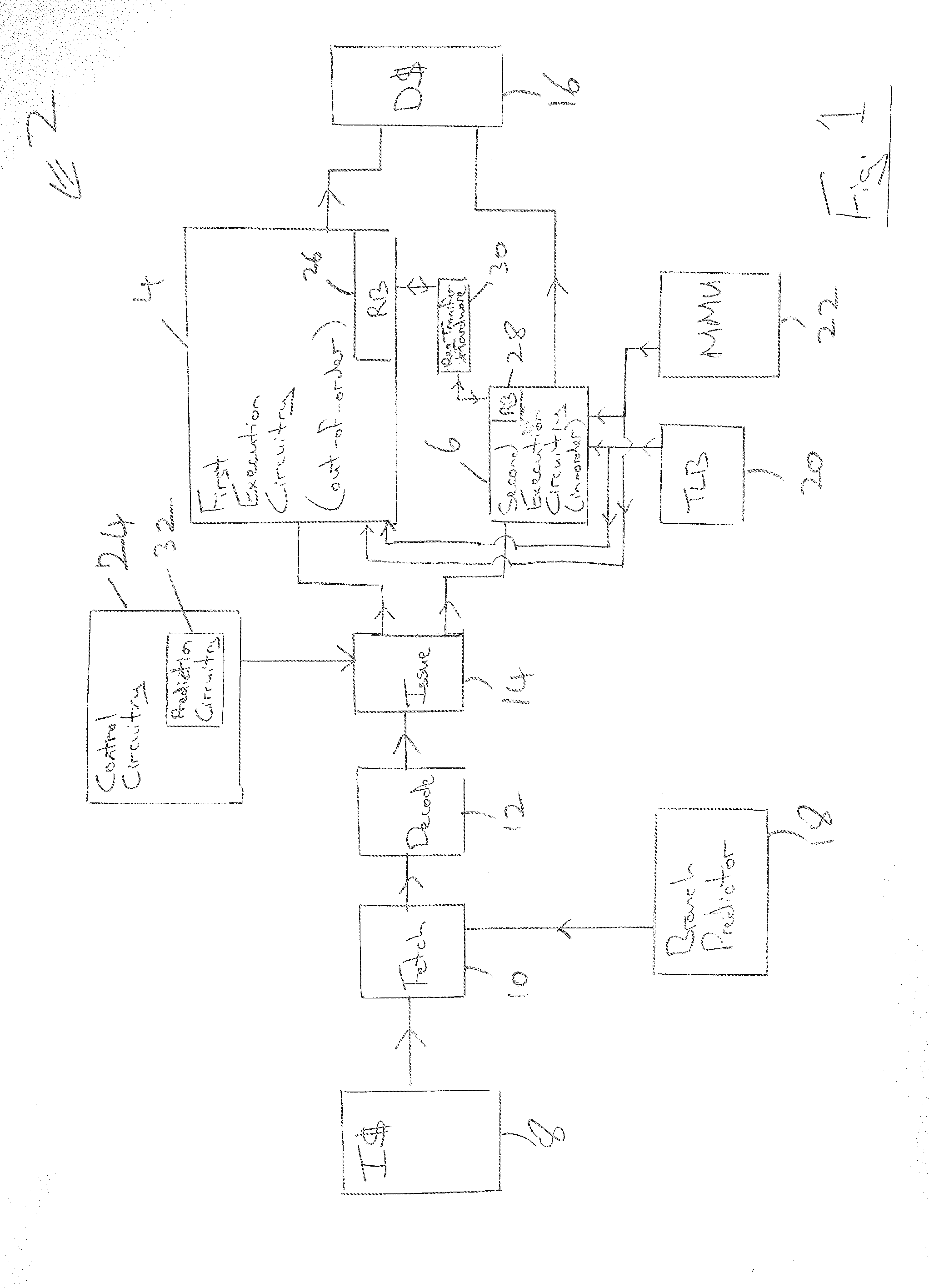
[0051]FIG. 1 schematically illustrates apparatus 2 for processing data, which may be formed on an integrated circuit, for example, as part of a system-on-chip integrated circuit. The apparatus 2 includes first execution circuitry 4 and second execution circuitry 6. The first execution circuitry 4 comprises multiple execution pipelines, such as arithmetic pipelines, load / store pipelines, SIMD pipelines, floating point pipelines etc, which are configured to support out-of-order program execution. It will be appreciated by those in this technical field that such execution circuitry will yield a high performance in terms of the number of instructions per cycle which may be executed, but will typically have the disadvantage of consuming a higher level of power. The second execution circuitry 6 comprises pipelines, such as arithmetic, load / store, SIMD, vector, floating point etc, that are capable of supporting in-order execution. This second execution circuitry will give a lower performan...


PUM


Abstract

An apparatus 2 for processing data includes first execution circuitry 4, such as an out-of-order processor, and second execution circuitry 6, such as an in-order processor. The first execution circuitry 4 is of higher performance but uses more energy than the second execution circuitry 6. Control circuitry 24 switches between the first execution circuitry 4 being active and the second execution circuitry 6 being active. The control circuitry includes prediction circuitry which is configured to predict a predicted identity of a next sequence of program instructions to be executed in dependence upon a most recently executed sequence of program instructions and then in dependence upon this predicted identity to predict a predicted execution target corresponding to whether the next sequence of program instructions should be executed by the first execution circuitry or the second execution circuitry.

Description

BACKGROUND OF THE INVENTION[0001]1. Field of the Invention[0002]This invention relates to the field of data processing systems. More particularly, this invention relates to the field of data processing systems having a plurality of execution mechanisms for executing program instructions and between which a selection may be made as to which execution mechanism is active to execute the stream of program instructions at a given time.[0003]2. Description of the Prior Art[0004]It is known to provide data processing systems, such as those employing the techniques of the big.LITTLE processors designed by ARM Limited of Cambridge, England, which incorporate multiple execution mechanisms among which an active execution mechanism is selected. These processors typically include a low performance and low power processor core together with a high performance and high power processor core. When the processing workload is such that high performance is not required, then the processing is switched ...

Claims


Application Information

Patent Timeline
Patent Type & Authority Applications(United States)
IPC IPC(8): G06F9/30
CPCG06F9/30058G06F9/3836G06F1/329G06F1/3293Y02D10/00
Inventor PADMANABHA, SHRUTILUKEFAHR, ANDREWDAS, REETUPARNAMAHLKE, SCOTT
Owner RGT UNIV OF MICHIGAN
Why Eureka
Try Eureka