Organic Light Emitting Device

a light-emitting device and organic technology, applied in the direction of solid-state devices, semiconductor devices, thermoelectric devices, etc., can solve the problems of reducing emission efficiency, consumption of consumption power, and limitations in brightness and contrast, and achieve enhanced emission efficiency, enhanced luminance, and enhanced service life

Active Publication Date: 2015-06-04
LG DISPLAY CO LTD
View PDF25 Cites 26 Cited by
  • Summary
  • Abstract
  • Description
  • Claims
  • Application Information

AI Technical Summary

Benefits of technology

[0020]An object of the present invention is to provide an organic light emitting device in which emission efficiency is enhanced by using a micro cavity structure.
[0021]Another object of the present invention is to provide an organic light emitting device in which luminance is enhanced by using a micro cavity structure.
[0022]Another object of the present invention is to provide an organic light emitting device in which a service life is enhanced by using a micro cavity structure.
[0023]Another object of the present invention is to provide an organic light emitting device in which a viewing angle is improved by using a micro cavity structure.

Problems solved by technology

The LCD devices use a backlight as a separate light source, and have technical limitations in brightness and contrast.
However, the method has a problem in which consumption power is consumed in a case of increasing luminance.
Also, the method has a problem in which emission efficiency is lowered when a light emitting material is changed for securing a long service life.
In addition, when a light emitting material is changed for increasing a light efficiency of each of a red pixel, a green pixel, and a blue pixel, a sense of color and a viewing angle are not satisfied in characteristic.
However, due to an emission structure of an organic light emitting device, a luminance Cd of a unit area A is limited.
Also, since a current increases for enhancing luminance, a reliability of a device is degraded, and consumption power increases.
Moreover, among pixels of three colors of the organic light emitting device, a blue pixel has a shorter service life than those of a red pixel and a green pixel, and in manufacturing a display panel having the pixels of three colors, a service life of the display panel cannot be ensured.

Method used


Image

  • Organic Light Emitting Device
  • Organic Light Emitting Device
  • Organic Light Emitting Device

Examples


first embodiment

Experiment Conditions of First Embodiment of the Present Invention

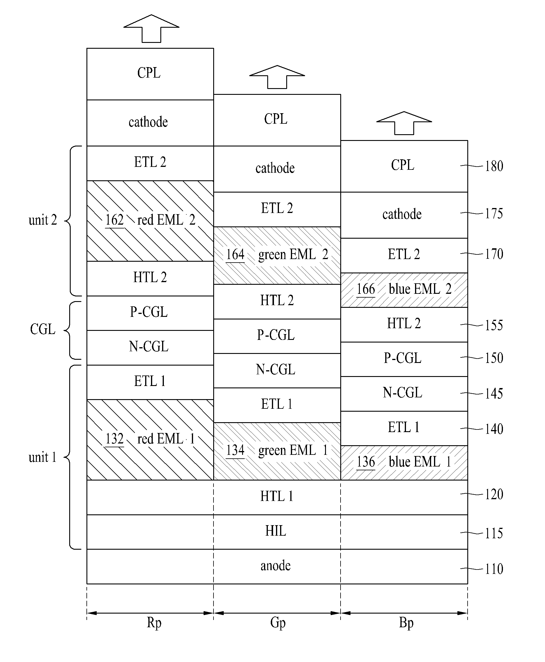
[0132]A first electrode (an anode electrode) 110 is a reflective electrode, and is formed in a structure where an ITO layer (a thickness: 70 Å), a reflective layer (APC, a thickness: 100 Å), and an ITO layer (a thickness: 70 Å) are stacked. In this case, the reflective layer (APC) is formed of an alloy which contains silver (Ag) by 90% or more.

[0133]The first electrode (the anode electrode) 110 is formed in units of one unit pixel. One unit pixel is composed of a red pixel, a green pixel, and a blue pixel of three colors, and the pixels of three colors are divided by a bank (not shown).

[0134]A hole injection layer (HIL) 115 is formed by depositing an HAT-CN material on the first electrode (the anode electrode) 110 to a thickness of 10 nm. A hole transport layer (HTL) 120 is formed by depositing NPD on the HIL 115 to a thickness of 37.5 nm.

[0135]A first red EML (red EML1) 132 is formed in a red pixel area Rp on a first...


PUM


Abstract

Disclosed is an organic light emitting device. The organic light emitting device includes a first emission unit configured to include a first red emission layer which emits red light, a first green emission layer which emits green light, and a first blue emission layer which emits blue light, a second emission unit configured to include a second red emission layer which emits red light, a second green emission layer which emits green light, and a second blue emission layer which emits blue light, a charge generation layer disposed between the first emission unit and the second emission unit, a first electrode formed as a reflective electrode, and configured to supply an electric charge having a first polarity to the first emission unit and the second emission unit, and a second electrode configured to supply an electric charge having a second polarity to the first and second emission units.

Description

CROSS-REFERENCE TO RELATED APPLICATIONS[0001]This application claims the benefit of Korean Patent Application No. 10-2013-0147742 filed on Nov. 29, 2013, which is hereby incorporated by reference as if fully set forth herein.BACKGROUND OF THE INVENTION[0002]1. Field of the Invention[0003]The present invention relates to an organic light emitting device, and more particularly, to an organic light emitting device, having a micro cavity emission structure, which satisfies a sense of color and in which emission efficiency and a service life are enhanced.[0004]2. Discussion of the Related Art[0005]To date, liquid crystal display (LCD) devices are being widely used as flat panel display devices. The LCD devices use a backlight as a separate light source, and have technical limitations in brightness and contrast. On the other hand, since organic light emitting devices self-emit light, the organic light emitting devices do not need a separate light source and have relatively better brightne...

Claims


Application Information

Patent Timeline
Patent Type & Authority Applications(United States)
IPC IPC(8): H01L51/50H01L27/32H01L51/52
CPCH01L51/5044H01L27/3209H01L51/5265H10K50/852H10K59/35H10K50/19H10K50/12H10K50/125H10K50/11H10K59/32
Inventor LEE, SE HEE
Owner LG DISPLAY CO LTD
Why Eureka
Try Eureka