Driving tool

a technology of driving tools and cylinders, applied in the field of driving tools, can solve problems such as insufficient or excessive air compression, and achieve the effect of smooth and reliable performan

Active Publication Date: 2015-06-11
MAKITA CORP
View PDF18 Cites 42 Cited by
  • Summary
  • Abstract
  • Description
  • Claims
  • Application Information

AI Technical Summary

Benefits of technology

[0004]However, in the above-described driving tool, if the first piston does not stop at the prescribed (most appropriate) position (in particular, its bottom dead center) after conclusion of the driving operation, then problems might arise during the next operation to drive the next driven article, such as an insufficient or excessive compression of air during the next driving operation. Accordingly, one non-limiting object of the present disclosure is to provide one or more techniques that enable multiple driving operations (including, e.g., so-called “continuous operations”) to be smoothly and reliably performed with such a driving tool.
[0007]According to the first aspect of the present disclosure, even if the first piston is not positioned at its bottom dead center (or within a predetermined range about its bottom dead center) after a driving operation has concluded, the stopped position of the first piston is made to more closely approach bottom dead center after the next driving operation. That is, the driving and / or braking of the first piston is / are adjusted such that the stopped position of the first piston is closer to its bottom dead center. In this case, in a third driving operation that follows the second driving operation, the movement of the first piston will be started from its bottom dead center, or closer thereto than if no modification of the braking control had taken place. Consequently, multiple driving operations can be performed in succession more smoothly, reliably and accurately; in particular the amount of force applied to the driven article (fastener) in each driving operation remains constant, or at least substantially constant. That is, by ensuring the compression (first) piston is positioned at (or close to) its bottom dead center prior to each driving operation, the quantity of compressed air generated inside the first cylinder will be constant, or at least substantially constant, in every driving operation. As a result, the driving speed of the driven articles remains stable (at least substantially constant) over a plurality of driving operations. Such an embodiment is particularly useful in continuous driving operations, in which multiple driving operations are performed successively, usually in a relative short time period, as will be further discussed below.
[0009]According to the above-described aspect, the stopped position of the first piston after completion of the second driving operation is adjusted by modifying (changing, shifting or adjusting) the braking start timing. Accordingly, it is possible to easily modify the drive control (or brake control), and thus the stopped position, of the first piston.
[0017]According to the above-described aspect, the sensor is configured to indirectly detect the position of the first piston by measuring the (rotational or angular) position of the crankshaft, the linking member, or the motor rotary shaft, instead of directly detecting the (linear) position of the first piston. In some embodiments of the present teachings, it may be difficult to directly measure the position of the first piston because it is housed inside the first cylinder. Nevertheless, according to the present aspect, the position of the first piston can be easily and reliably detected (determined) without directly measuring it.

Problems solved by technology

However, in the above-described driving tool, if the first piston does not stop at the prescribed (most appropriate) position (in particular, its bottom dead center) after conclusion of the driving operation, then problems might arise during the next operation to drive the next driven article, such as an insufficient or excessive compression of air during the next driving operation.

Method used


Image

  • Driving tool
  • Driving tool
  • Driving tool

Examples


first embodiment

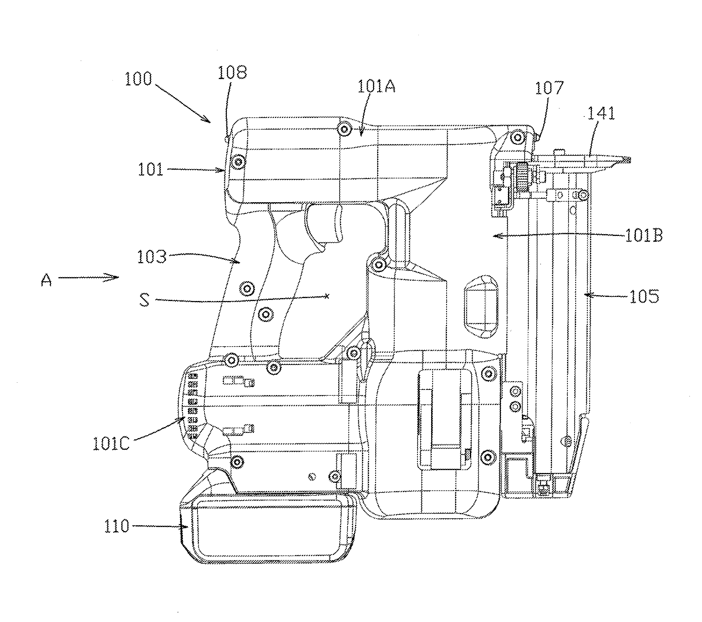
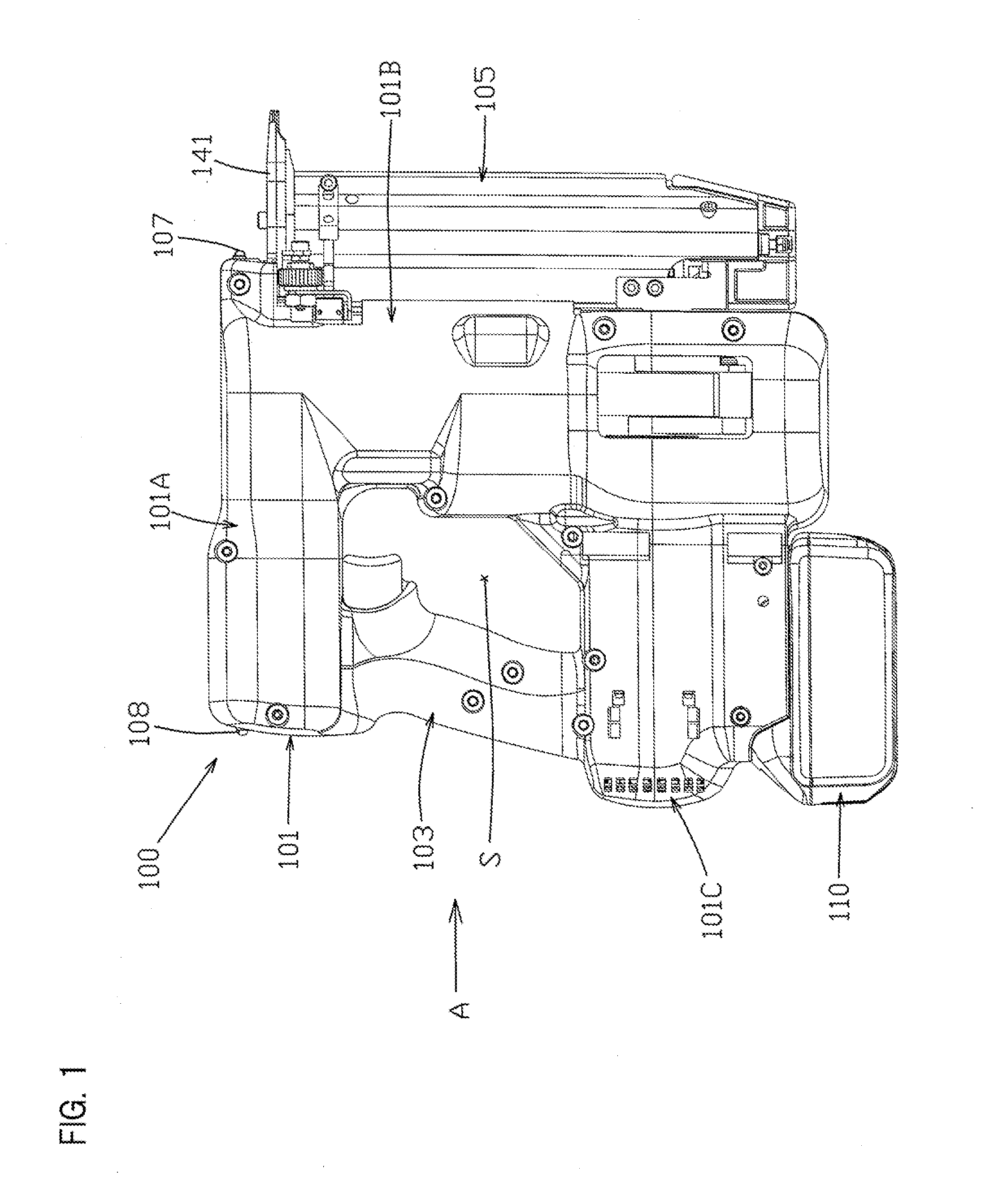
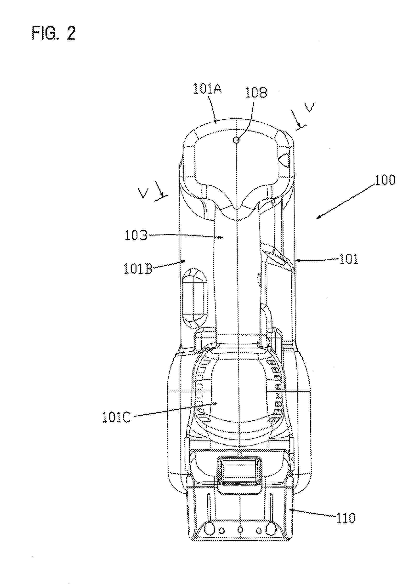
[0031]A first embodiment will be explained below, with reference to FIG. 1 through FIG. 9, as a representative embodiment of the present disclosure. The first embodiment is explained using an electro-pneumatic nailer as one non-limiting example of a driving tool according to the present disclosure. As shown in the overall views of FIG. 1 and FIG. 2, a nailer (nail gun) 100 may principally comprise a main-body housing 101 and a magazine 105. The main-body housing 101 is defined as a tool main body and forms an outer wall (shell) of the nailer 100. The magazine 105 is loaded with nails (not illustrated), which serve as driven articles that are to be driven into a workpiece. The main-body housing 101 is formed by joining a pair of substantially symmetrical housings together. The main-body housing 101 integrally comprises a handle (handle part) 103, a driving-mechanism housing part 101A, a compressing-apparatus housing part 101B, and a motor-housing part 101C.

[0032]The handle part 103, ...

second embodiment

[0081]In the above-described first embodiment, the control unit 109 is configured such that, in the first driving operation and in the second driving operation, it modifies the braking start timing, e.g., by changing a stored amount of time or by changing a stored crank angle when the braking of the compression piston 133 is initiated. However, in the second embodiment that will be described in the following, the braking force may be modified without modifying the braking start timing, in order to achieve a stopped position of the compression piston 133 after the second driving operation that is closer to its bottom dead center than after the first driving operation. It is noted that, except for the modification of the braking control, the configuration of the nailer 100 may be the same as that of the first embodiment; therefore the same reference numerals are assigned to the same structural elements as the first embodiment and an explanation of such structural elements may be omitt...


PUM


Abstract

An electro-pneumatic tool drives a fastener into a workpiece by energizing an electric motor to drive a first piston and generate compressed air in a first cylinder. The compressed air is then supplied to a second cylinder and causes a second piston to move and drive the fastener into the workpiece. After the first piston has passed through its top dead center, braking is applied to the first piston according to one or more braking parameters. Then, if a control unit determines that the first piston has come to a stop at a position that is outside a predetermined range about the bottom dead center of the first piston, one or more of the braking parameters is changed in a subsequent fastener driving cycle to cause the first piston to stop closer to its bottom dead center after conclusion of the subsequent fastener driving cycle.

Description

CROSS-REFERENCE TO RELATED APPLICATION[0001]The present application claims priority to Japanese patent application serial number 2013-256058 filed on Dec. 11, 2013, the contents of which are incorporated fully herein by reference.TECHNICAL FIELD[0002]The present invention generally relates to a driving tool that drives a driven article, such as a fastener, into a workpiece.BACKGROUND ART[0003]A driving tool that drives a driven article (e.g., a fastener) into a workpiece is described in U.S. Pat. No. 8,079,504. Inside a first cylinder of the aforementioned driving tool, a first piston generates compressed air, which is communicated to a second cylinder. This compressed air causes a second piston inside the second cylinder to move and to thereby strike the driven article. Thus, the driving tool is configured to drive the driven article toward and into the workpiece. In addition, this driving tool comprises a sensor that detects the position of the first piston during the operation cy...

Claims


Application Information

Patent Timeline
Patent Type & Authority Applications(United States)
IPC IPC(8): B25C1/04F15B15/14F15B9/09
CPCB25C1/047F15B2211/8855F15B15/149F15B9/09B25C1/06
Inventor KATO, ITSUKU
Owner MAKITA CORP
Why Eureka
Try Eureka