Image recording apparatus, image recording method, and storage medium
a technology of image recording and recording method, which is applied in the field of image recording apparatus, image recording method, and storage medium, can solve problems such as color unevenness in recorded images, and achieve the effect of suppressing both color unevenness
- Summary
- Abstract
- Description
- Claims
- Application Information
AI Technical Summary
Benefits of technology
Problems solved by technology
Method used
Image
Examples
first embodiment
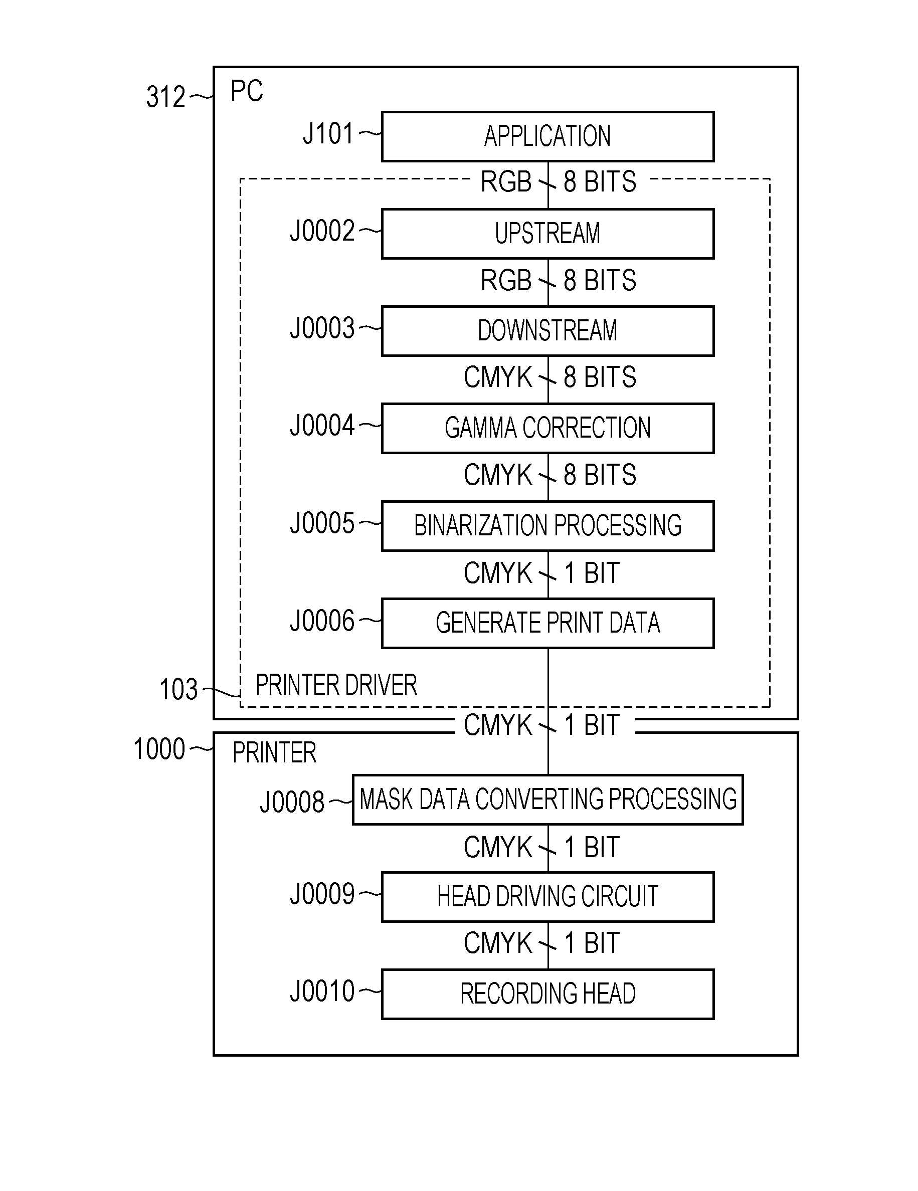
[0050]A first embodiment will be described. FIG. 5 is a perspective view partially illustrating the configuration of an image recording apparatus according to the present embodiment. FIG. 6 is a side view partially illustrating the configuration of the image recording apparatus according to the present embodiment.
[0051]A housing 1 is provided within the image recording apparatus 1000. A platen 2 is disposed upon this housing 1. Also provided within the housing 1 is a suctioning device 4 to suction a recording medium 3, which has the form of a sheet, to the platen 2. A main rail 5 is disposed in the longitudinal direction of the housing 1, so as to support a carriage 6 which reciprocally moves in the X direction (scanning direction). Mounted on the carriage 6 is an ink-jet type recording head 7. The recording head 7 may be any of a variety of ink-jet types, such as those using heating elements, those using piezoelectric elements, and so forth. A carriage motor 8 serves as a driving s...
second embodiment
[0123]Description has been made in the first embodiment regarding a configuration where a so-called joint head is used, which has multiple discharge orifice rows arrayed in the Y direction. Conversely, a second embodiment will be described where recording is performed using a recording head made up of a single discharge orifice row. Note that description of portions which are the same as those described in the first embodiment above will be omitted here.
[0124]FIG. 22 is a schematic diagram illustrating a recording head used in the present embodiment and mask patterns applied in the present embodiment. A recording head 130, having 1,280 discharge orifices 30 for discharging ink arrayed in the Y direction, is used in the present embodiment. These discharge orifices 30 are divided into eight discharge orifice groups B1 through B8, each having 160 discharge orifices 30. An image is recorded by performing eight scans as to a unit region on the recording medium, with the discharge orifice...
third embodiment
[0127]Description has been made in the first and second embodiments regarding a configuration where two out of multiple mask patterns corresponding to the scans are classified in one mask pattern group. Conversely, a third embodiment will be described where three mask patterns are classified in one mask pattern group. Note that description of portions which are the same as those described in the first and seconds embodiments above will be omitted here.
[0128]FIG. 23 is a diagram of mask patterns applied in the present embodiment. An image is recorded by performing twelve scans as to a unit region on the recording medium in the present embodiment. Note that the recording head used in the present embodiment is the same as the recording head used in the first embodiment.
[0129]The rows 22Ka and 22Kb in the recording head used in the present embodiment are each divided into six discharge orifice groups, discharge orifice group C1 through discharge orifice group C6, and discharge orifice g...
PUM
 Abstract
Description
Claims
Application Information
 - R&D
- Intellectual Property
- Life Sciences
- Materials
- Tech Scout
- Unparalleled Data Quality
- Higher Quality Content
- 60% Fewer Hallucinations
Browse by: Latest US Patents, China's latest patents, Technical Efficacy Thesaurus, Application Domain, Technology Topic, Popular Technical Reports.
© 2025 PatSnap. All rights reserved.Legal|Privacy policy|Modern Slavery Act Transparency Statement|Sitemap|About US| Contact US: help@patsnap.com


