
Battery and unmanned aerial vehicle with the battery

a technology for unmanned aerial vehicles and batteries, applied in the direction of battery/fuel cell control arrangements, charging stations, transportation and packaging, etc., can solve the problems of bringing an instant high voltage, sparks can have at least two harmful effects, and can be produced at the contact point, so as to improve the discharge control mechanism

Active Publication Date: 2015-06-11
SZ DJI TECH CO LTD
View PDF14 Cites 86 Cited by
  • Summary
  • Abstract
  • Description
  • Claims
  • Application Information

AI Technical Summary

Benefits of technology

The patent text describes a power supply with a discharge control mechanism that can help prevent damage to electrical equipment and battery explosions. The power supply includes an electronic switch and an input device for controlling the switch. The power supply circuit also includes a power measurement device and an indication device to show the remaining battery power. The power supply can provide power to a device to be powered, such as a propulsion unit of a UAV, and the level of charge can be calculated using the current measurement device. The power supply circuit can be connected to an external power source to control the power supply. Overall, the power supply has improved discharge control mechanisms to protect against damage and improve safety.

Problems solved by technology

However, during the process of connecting the interface between the two devices or when the electromechanical switch is closed, sparks can be produced at the contact point.
The sparks can have at least two harmful effects.
First, the sparks can bring an instantly high voltage, often 2-3 times higher than the battery voltage.
Second, the sparks can burn and erode the contact point, resulting in increased resistance or a bad connection at the contact point, which can be a safety risk (e.g., for movable objects, such as unmanned aerial vehicles (UAVs)).
Furthermore, due to large current and a lack of charge / discharge protection, the batteries are often damaged due to over-charge and / or over-discharge.
There is also a possibility of battery explosion or bulging due to over-charge.
Also, the user is forced to rely on the measurement of voltage to determine the remaining battery power, which can be very inaccurate.
Battery depletion can be dangerous (e.g., during flight of a UAV).

Method used


Image

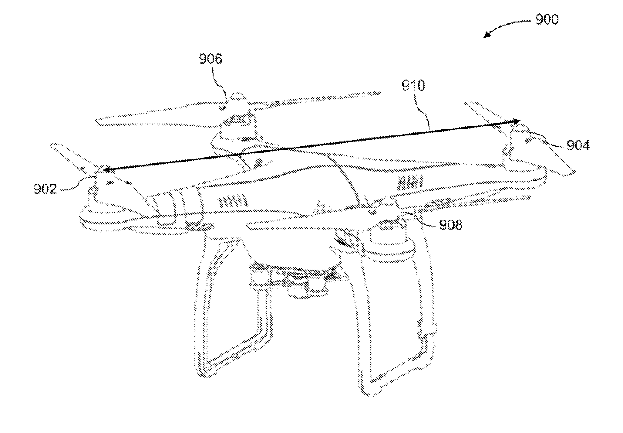
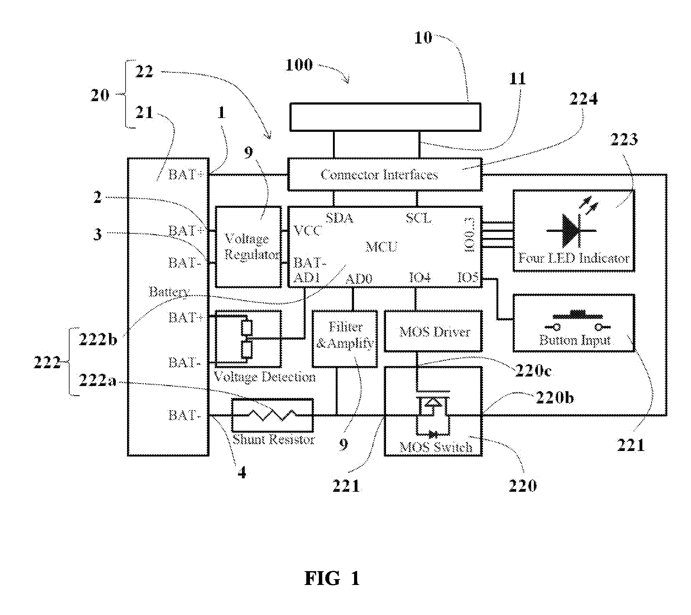
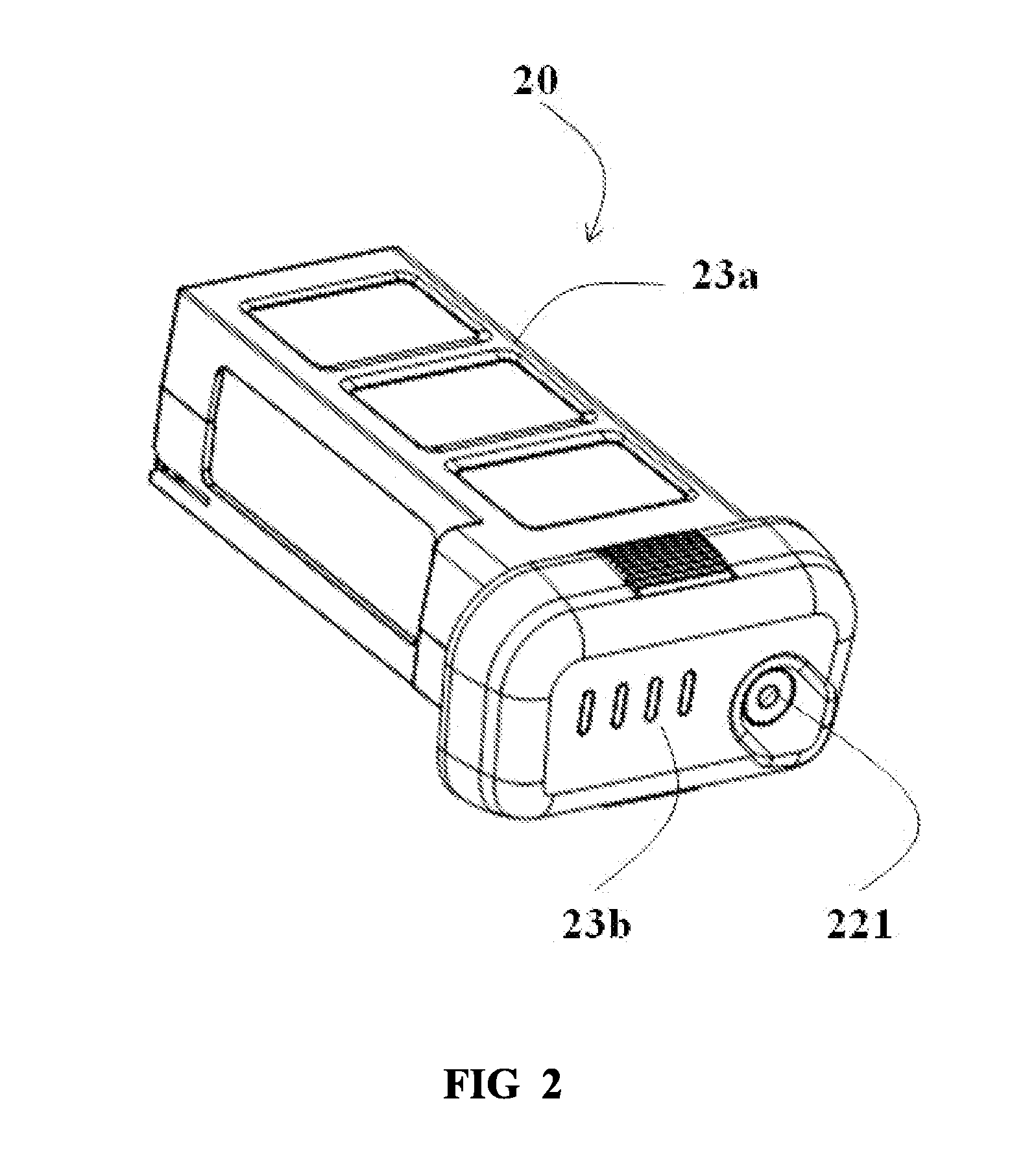
  • Battery and unmanned aerial vehicle with the battery
  • Battery and unmanned aerial vehicle with the battery
  • Battery and unmanned aerial vehicle with the battery

Examples


Embodiment Construction

[0053]The systems, methods, and devices of the present invention provide a power supply with a power supply control assembly and a device with the power supply. In some cases, the device is a movable object, such as an unmanned aerial vehicle (UAV). The power supply may be or may include a battery or battery pack. A power supply control assembly may include a power supply circuit. The power supply control may overcome challenges related to lack of discharge control. The power supply circuit can be connected to the power supply. The power supply can discharge through the power supply circuit. The power supply circuit can comprise an electronic switch and an input device, with the electronic switch being electrically connected to the power source for controlling power on or off of the power supply. The input device can be electrically connected to the electronic switch for controlling the switched-on or switched-off state of the electronic switch. Use of the electronic switch which ma...


PUM


Abstract

The disclosure provides a battery which can include a power supply and power supply circuit, the power supply circuit connected to the power supply. The power supply can discharge through the power supply circuit. An electronic switch can control the power-on or off of the power supply, thereby avoiding the generation of sparks during the power on process and allowing for the normal use of the battery and the safety of the aircraft. The disclosure also provides an aircraft having the battery.

Description

CROSS-REFERENCE[0001]This application is a continuation of International Application No. PCT / CN2014 / 071940, filed on Feb. 10, 2014, which claims priority from Chinese Patent Application No. 201310659214.5, filed on Dec. 6, 2013. The above-referenced applications are hereby incorporated by reference.BACKGROUND[0002]Unmanned vehicles such as unmanned aerial vehicles (UAVs) can be used for performing surveillance, reconnaissance, and exploration tasks for military and civilian applications. Such unmanned vehicles typically include a propulsion system for remote controlled and / or autonomous movement with the surrounding environment. For example, the unmanned vehicles may have a power supply that powers a device of the unmanned vehicle, such as the propulsion system.[0003]Existing systems of battery or power output control for unmanned vehicles, however, can be less than ideal. The batteries traditionally used in UAVs, for example, can have very large currents and can lack a discharge co...

Claims


Application Information

Patent Timeline
IPC IPC(8): B60L11/18
CPCB60L11/1809B60L2200/10B60L2260/32B60L53/80B60L58/22B60L58/15Y02T10/70Y02T10/7072Y02T90/16B64U50/19H02J7/00B60L58/12B64U30/20B64U2201/20B64C39/024
Inventor ZHAO, TAO
Owner SZ DJI TECH CO LTD
Learn More