Eureka AIR delivers breakthrough ideas for toughest innovation challenges, trusted by R&D personnel around the world.

Light Emitting Diode Device

Active Publication Date: 2015-06-11
DELTA ELECTRONICS INC
View PDF5 Cites 4 Cited by
  • Summary
  • Abstract
  • Description
  • Claims
  • Application Information

AI Technical Summary

Benefits of technology

The objective of this patent is to create an LED device that is thinner, has less light loss, and is safer. The invention achieves this by connecting the metal housing and lenses directly, which minimizes the distance between them and reduces light loss. This results in a thinner LED device with lower light loss and higher safety.

Problems solved by technology

However, the thickness of the resilient member can directly affect the distance between the lens member and the cover.
When the distance between the lens member and the cover becomes larger, more light beams will be trapped and blocked inside the LED apparatus.
Besides, if the cover is made of metal material, the minimization of the thickness of the resilient member has a critical limitation due to the arcing issue of the cover and the safety barrier.

Method used


Image

  • Light Emitting Diode Device
  • Light Emitting Diode Device
  • Light Emitting Diode Device

Examples


Embodiment Construction

[0024]The present invention will be apparent from the following detailed description, which proceeds with reference to the accompanying drawings, wherein the same references relate to the same elements.

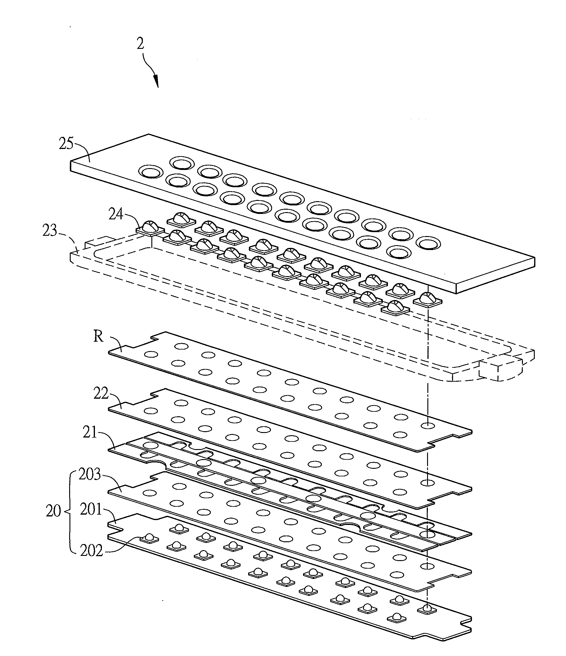
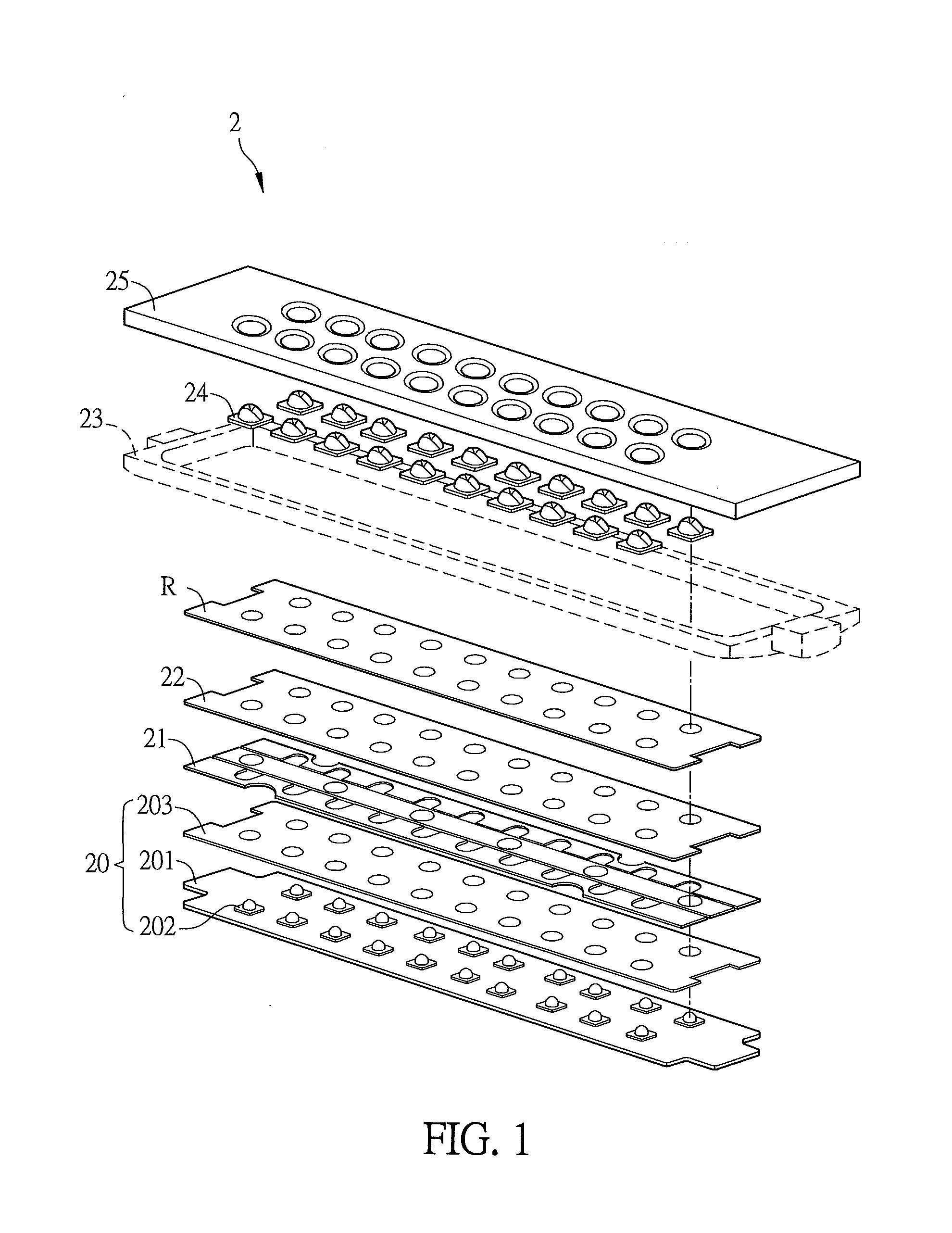
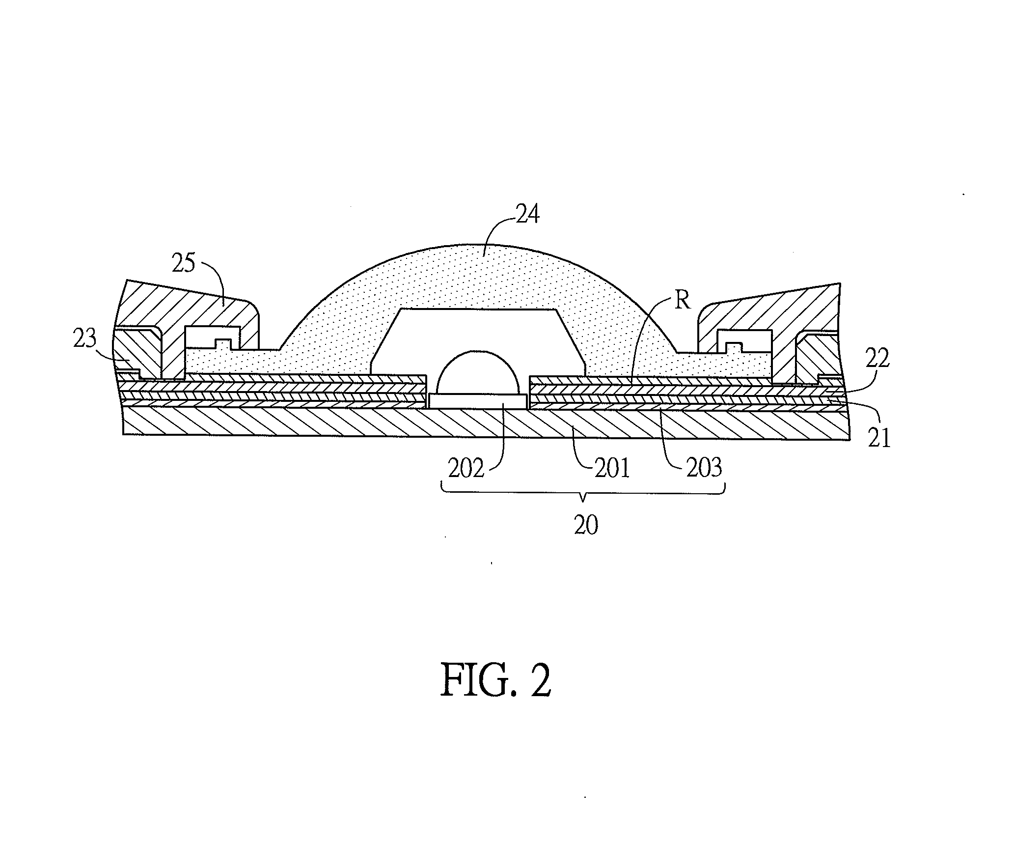
[0025]FIG. 1 is an exploded view of an LED device 2 according to a preferred embodiment of the invention, and FIG. 2 is a partial enlarged sectional view of the LED device 2 of FIG. 1.

[0026]Referring to FIGS. 1 and 2, the LED device 2 includes a light emitting module 20, a metal barrier 21, a plurality of lenses 24, an isolation structure 23 and a metal housing 25. Besides, the LED device 2 may further include a first insulating layer 22.

[0027]The light emitting module 20 has a plurality of light emitting diodes 202 serving as light sources.

[0028]In addition, the LED device 2 may further have a water-proof function, so that it can be adapted to the outdoor applications such as the streetlamps or vehicle lamps. Preferably, the isolation structure 23 is disposed on the metal barrier 21....


PUM


Abstract

A light emitting diode (LED) device is disclosed. The LED device includes a light emitting module, a metal barrier, an isolation structure, a metal housing and a plurality of lenses. The light emitting module has a plurality of light emitting diodes serving as light sources. The metal barrier is disposed above the light emitting module, and the light emitting diodes are exposed from the metal barrier. The isolation structure and the metal housing are disposed above the metal barrier. The lenses are disposed corresponding to the light emitting diodes. The lenses are directly fixed on the metal housing or located between the isolation structure and the metal housing.

Description

CROSS REFERENCE TO RELATED APPLICATIONS[0001]This Non-provisional application claims priority under 35 U.S.C. §119(a) on Patent Application No(s). 102223306 filed in Taiwan, Republic of China on Dec. 11, 2013, the entire contents of which are hereby incorporated by reference.BACKGROUND OF THE INVENTION[0002]1. Field of Invention[0003]The present invention relates to an illumination device and, in particular, to a light emitting diode (LED) device.[0004]2. Related Art[0005]Typically, the conventional LED lamp includes an LED module and a power supply. In order to achieve better conversion efficiency, the series voltage of the LED module is usually adjusted to fit the voltage provided from the power supply so as to minimize the loss in the voltage-dropout conversion. For example, if the power supply is connected to the city electricity, the series voltage of the LED module is preferably adjusted to 220V. However, when the output voltage of the DC terminal of the power supply is larger...

Claims


Application Information

Patent Timeline
IPC IPC(8): F21V15/01F21K99/00
CPCF21V15/01F21V15/011F21K9/50F21V5/007F21V31/005F21Y2105/10F21Y2115/10F21V15/012
Inventor WU, HSIANG-CHENHUANG, CHIH-YUANTIEN, KUN-MING
Owner DELTA ELECTRONICS INC
Why Eureka
Eureka Blog
Learn More