Demand response system

a demand response and demand technology, applied in the field of demand response systems, can solve problems such as inconvenience for users, and achieve the effect of reducing peak power rates and reducing electricity bills

Inactive Publication Date: 2015-06-11
SAMSUNG ELECTRONICS CO LTD
View PDF19 Cites 4 Cited by
  • Summary
  • Abstract
  • Description
  • Claims
  • Application Information

AI Technical Summary

Benefits of technology

The invention provides a system that can change the energy output of products in response to a demand response program, to reduce peak power rates and lower electricity bills. The system includes a control unit that sends different levels of demand response with different power rates to products, such as appliances in a household. The products have a feature that stores information about the energy output of each level, and when a new level is received, the product changes its energy output to match the new level, reducing power consumption. This can be beneficial for reducing energy waste and lowering electricity bills for consumers.

Problems solved by technology

That is, the conventional DR system has been designed to limit the operation of household appliances in response to power rates, which may cause user inconvenience.

Method used


Image

  • Demand response system
  • Demand response system
  • Demand response system

Examples


Embodiment Construction

[0045]Reference will now be made in detail to the embodiments, examples of which are illustrated in the accompanying drawings, wherein like reference numerals refer to like elements throughout.

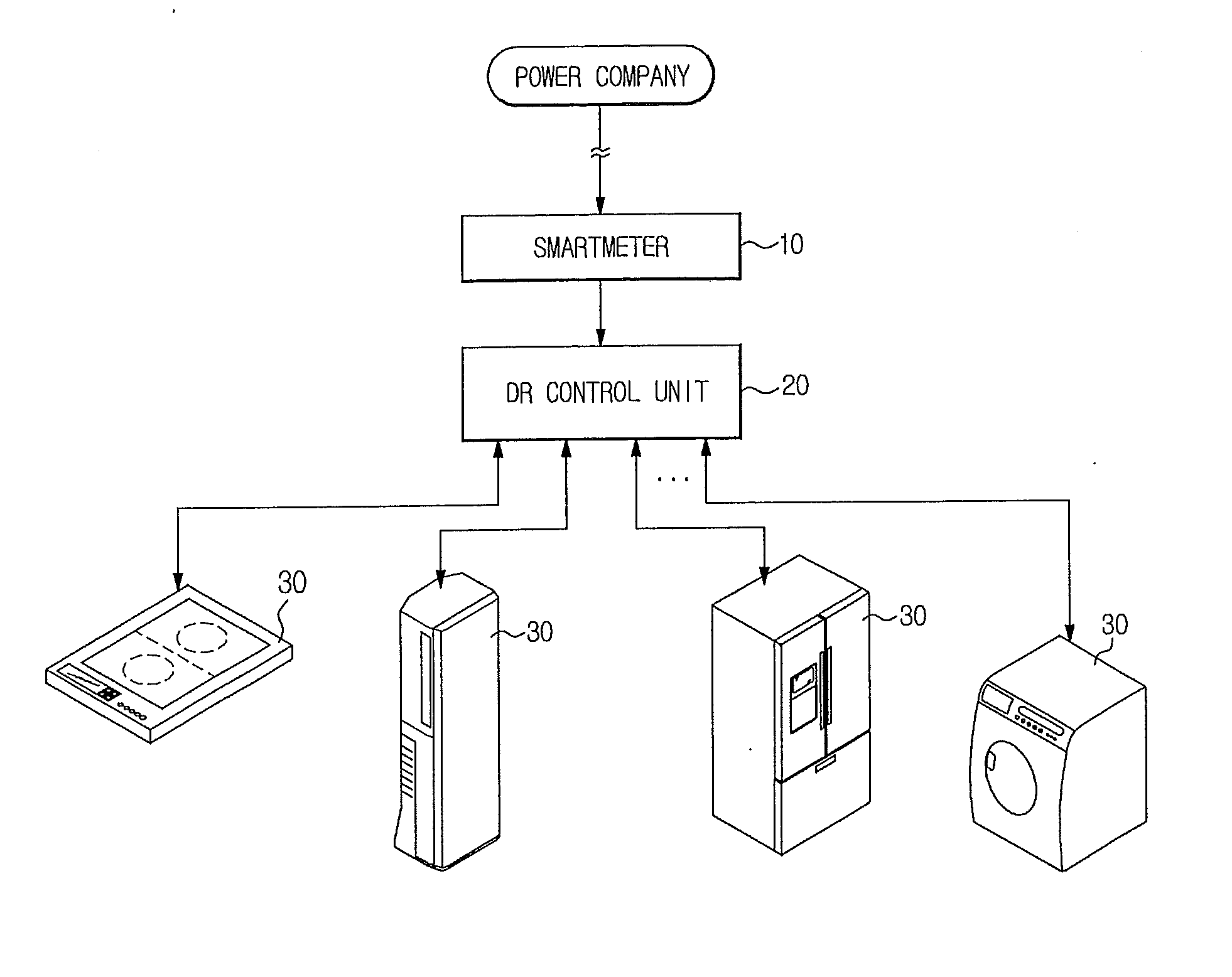
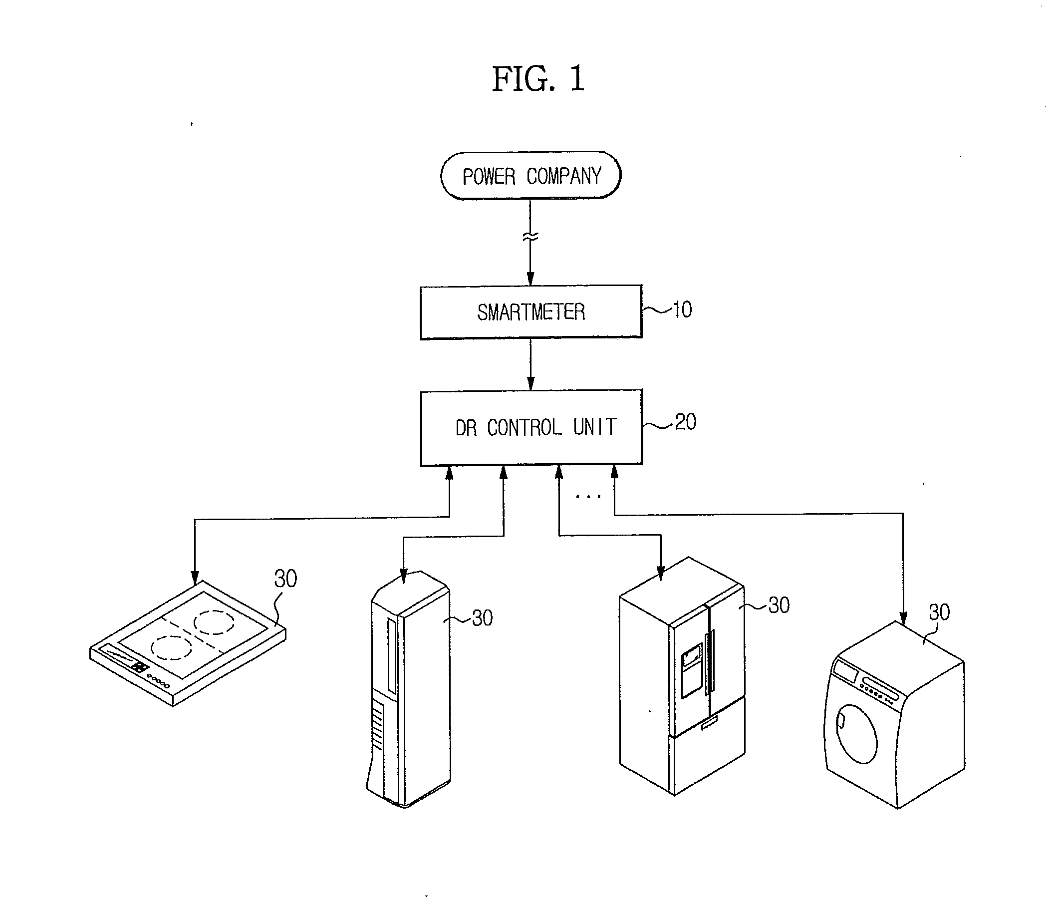
[0046]FIG. 1 is a configuration diagram illustrating a demand response (DR) system according to an embodiment.

[0047]Referring to FIG. 1, the DR system includes a smartmeter 10 installed in a home to transmit and receive information to and from a power company; a DR control unit 20 for receiving information about electric charges from the smartmeter 10; and respective household appliances 30 connected to the DR control unit 20 over a network.

[0048]Each household appliance 30 performs a desired function using power received through a power line.

[0049]The household appliance 30 may include all kinds of electric household appliances, for example, an induction heating cooker, an air-conditioner, a refrigerator, a washing machine, etc.

[0050]The DR control unit 20 receives power rate information from...


PUM


Abstract

A demand response (DR) system includes a DR control unit to generate different DR levels having different power rates for each power unit, and transmit a current DR level, and a household appliance to receive the DR level from the DR control unit, and differentially control energy output of a product in response to the received DR level so as to reduce power consumption of the product. As a result, the DR system reduces power consumption when power rates are high so as to reduce electricity bills.

Description

CROSS-REFERENCE TO RELATED APPLICATIONS[0001]This application is a Continuation Application of U.S. Ser. No. 12 / 929,873 filed Feb. 22, 2011, and claims the benefit of Korean Patent Application No. 10-2010-0018627, filed on Mar. 2, 2010 in the Korean Intellectual Property Office, the disclosures of which are incorporated herein by reference.BACKGROUND[0002]1. Field[0003]Embodiments relate to a demand response system for reducing power consumption during peak power rates so as to reduce electricity bills.[0004]2. Description of the Related Art[0005]Generally, it is necessary for a power system to balance demand and supply. This requirement of the power system is of importance to rational utilization of limited energy resources.[0006]For the aforementioned reasons, demand management is a focus of attention, and a number of studies are underway into demand response (DR) systems for advanced demand management.[0007]Demand response (DR) can be defined as variation in consumption format de...

Claims


Application Information

Patent Timeline
Patent Type & Authority Applications(United States)
IPC IPC(8): G05F1/66G05B15/02H04L12/28F24F11/00
CPCG05F1/66F24F11/006F24F2011/0071H04L12/2803G05B15/02G05B19/0428G05B2219/2642F24F11/47F24F11/52F24F11/64F24F11/30F24F11/62F24F11/58H02J3/00G06Q50/06G06Q10/10
Inventor KIM, HYUN KILIM, JAE MINPYUNG, SEONG UKJIN, SUN ILKIM, HYENG KYUNSEO, JAE YUJEONG, SEONG WOOKCHO, SUNG HOPARK, JUNG WONYANG, JANG BEOMSON, CHANG HOBAEK, YOUNG JIN
Owner SAMSUNG ELECTRONICS CO LTD
Why Eureka
Try Eureka