Image capturing apparatus and control method thereof

a technology of image capturing and control methods, which is applied in the field of image capturing apparatuses and control methods thereof, can solve the problems of affecting the appearance of through-the-lens images, inhibiting af accuracy, and affecting the accuracy of af, so as to maintain the quality of through-the-lens images displayed, without increasing processing time required

Inactive Publication Date: 2015-06-11
CANON KK
View PDF3 Cites 13 Cited by
  • Summary
  • Abstract
  • Description
  • Claims
  • Application Information

AI Technical Summary

Benefits of technology

[0016]The present invention has been made in consideration of the above situation, and makes it possible to maintain the quality of a through-the-lens image displayed in a display unit without increasing the processing time required to perform focus adjustment accurately.

Problems solved by technology

Such line flicker affects the appearance of through-the-lens images displayed in an LCD.
Meanwhile, in the case where the lines affected by the line flicker differ for each readout timing, or in other words, in the case where the line flicker fluctuates, the output of the focus evaluation value for each line will fluctuate due to the line flicker fluctuation; as a result, the correct peak position cannot be detected, which affects the accuracy of the AF.
Although doing so improves the appearance of the through-the-lens image, it does not result in an optimal exposure setting for AF processing, and conversely will sometimes inhibit the AF accuracy.
Recent devices have higher numbers of pixels, making it impossible to ignore even slight shifts in focus and increasing demand for more accurate focus adjustment.
However, there is a problem in that in the case of a high-luminance object, a point light source object, or the like, the influence thereof will result in a position that is not the in-focus position being erroneously determined as an in-focus position, and this problem cannot be solved even if measures are taken for cases where the in-focus position cannot be detected, as with Japanese Patent Laid-Open No. 2002-196220.
There is a further problem in that performing the AF search a plurality of times, at the appropriate exposure and at an exposure lower than the appropriate exposure, increases the amount of time required for the AF processing.
Furthermore, although the conventional technique disclosed in Japanese Patent Laid-Open No. 2008-130531 does stabilize the focus evaluation value by preventing fluctuations in line flicker, the focus evaluation value output drops within the AF frame in areas that overlap with lines where the exposure amount has dropped due to the line flicker, and thus the accuracy of the AF cannot be ensured.
Further still, the appearance of the through-the-lens image displayed in the LCD worsens due to the occurrence of the line flicker.

Method used


Image

  • Image capturing apparatus and control method thereof
  • Image capturing apparatus and control method thereof
  • Image capturing apparatus and control method thereof

Examples


first embodiment

[0047]Apparatus Configuration and Basic Operations

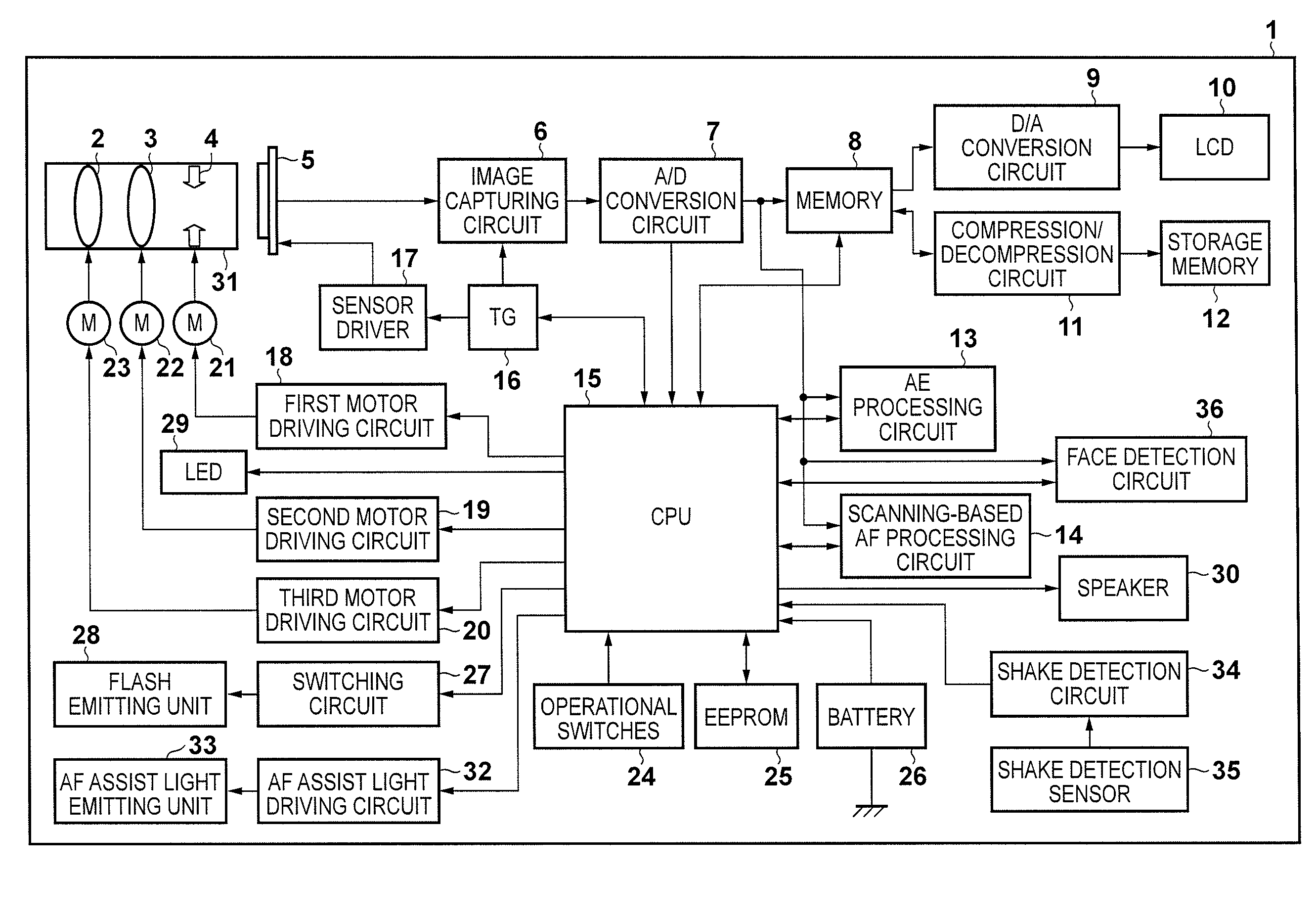
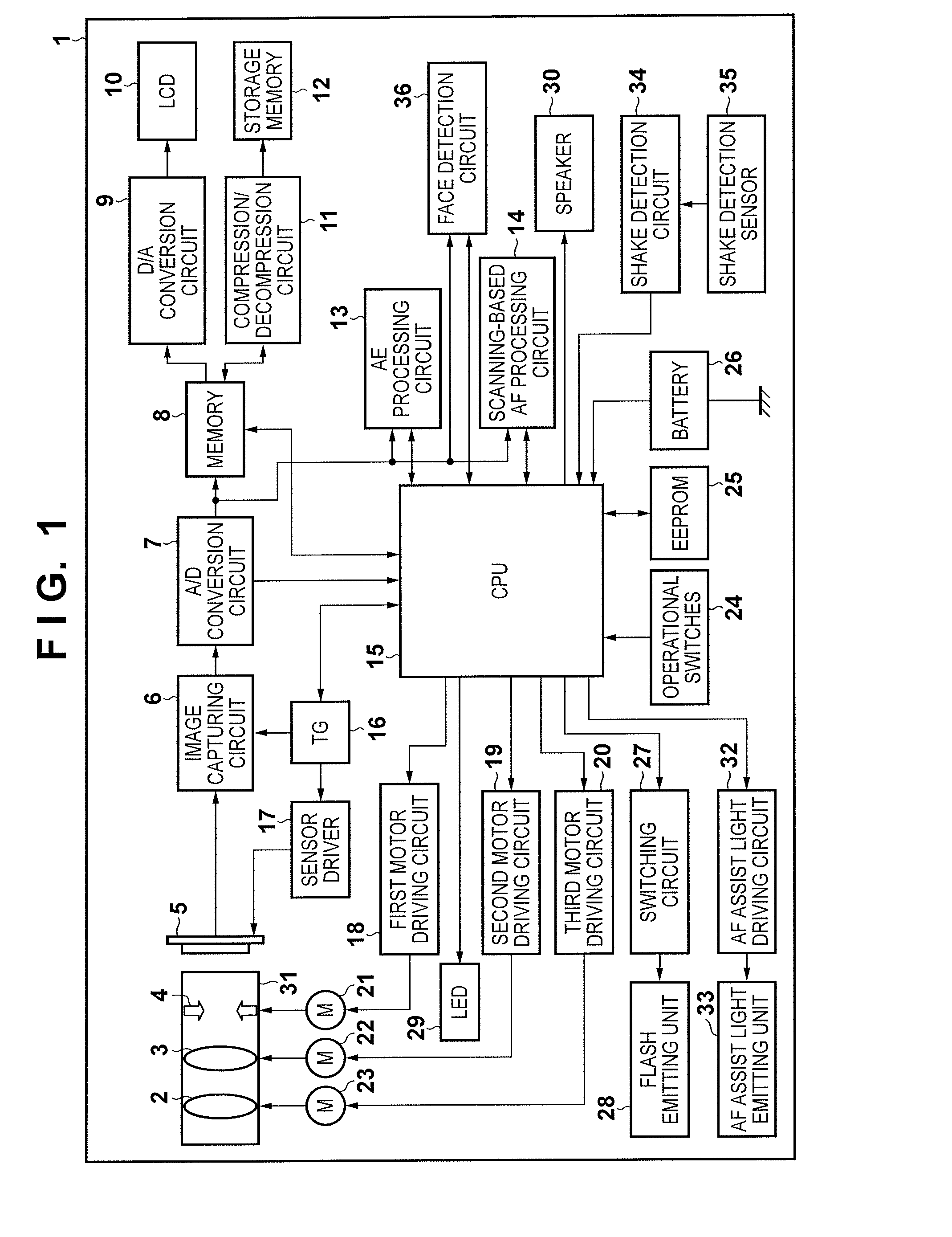
[0048]FIG. 1 is a block diagram illustrating the overall configuration of an image capturing apparatus according to a first embodiment of the present invention.

[0049]In FIG. 1, an image capturing apparatus 1 corresponds to a digital still camera, a digital video camera, or the like, for example. A zoom lens group 2 and a focus lens group 3 configure an optical imaging system. An aperture 4 controls a light flux amount that traverses the optical imaging system. The zoom lens group 2, the focus lens group 3, and the aperture 4 are configured within a lens barrel 31.

[0050]An object image that has traversed the optical imaging system is formed upon an image capturing surface of an image sensor 5 and is photoelectrically converted. An image capturing circuit 6 receives an electrical signal resulting from the photoelectric conversion performed by the image sensor 5 and generates a predetermined image signal by executing various types of im...

second embodiment

[0136]Next, a second embodiment of the present invention will be described. The second embodiment differs from the aforementioned first embodiment in that a process for roughly adjusting the focus (continuous AF) is carried out before SW1 turns on (that is, before an image capturing preparation instruction). This continuous AF is executed before determining whether or not a point light source is present within an AF frame, as will be described later. Note that the configuration of the image capturing apparatus 1 is the same as that illustrated in FIGS. 1 and 2, and thus descriptions thereof will be omitted.

[0137]Overall Flow of Image Capture Processing

[0138]The image capture processing according to the second embodiment will be described using the flowchart shown in FIG. 14.

[0139]As in the first embodiment, the image capture processing sequence is executed when the main power switch of the image capturing apparatus 1 is on and an operational mode of the image capturing apparatus is ...

third embodiment

[0160]Next, a third embodiment of the present invention will be described. The present third embodiment differs from the first embodiment in that a charge accumulation period at which pixels will not be saturated is searched out prior to SW1 turning on (prior to an image capturing preparation instruction), and the band of a band pass filter used during the normal image AF processing is switched based on the presence / absence of saturated pixels at the final charge accumulation period. Note that the configuration of the image capturing apparatus 1 is the same as that illustrated in FIGS. 1 and 2, and thus descriptions thereof will be omitted.

[0161]In the present third embodiment, the scanning-based AF processing circuit 14 detects a number of saturated pixels in the AF region and outputs that number, in addition to the AF evaluation value.

[0162]Image Capture Processing

[0163]The image capture processing according to the third embodiment will be described using the flowchart shown in FI...


PUM


Abstract

In an image capturing apparatus, an image sensing unit has a plurality of pixels and photoelectrically converts an object image formed by an optical imaging system including a focus lens and outputs an electrical image signal, a control unit controls at least a readout rate or an exposure condition independently for different regions of the image sensing unit, and a calculation unit calculates a plurality of focus evaluation values based on image signals read out from the pixels present in a focus detection area in one of the plurality of different regions at different focus lens positions, and find an in-focus position of the focus lens based on the focus evaluation values. The control unit takes an image signal read out from a first region among the plurality of different regions as an image signal for display.

Description

BACKGROUND OF THE INVENTION[0001]1. Field of the Invention[0002]The present invention relates to image capturing apparatuses and control methods thereof, and particularly relates to image capturing apparatuses that perform focus adjustment using an image signal obtained by an image sensor that photoelectrically converts an object image formed by an optical imaging system, and to control methods thereof.[0003]2. Description of the Related Art[0004]Conventionally, when a digital still camera, a video camera, or the like carries out autofocus (AF), a method is employed in which a focus lens position having maximum high-frequency components in a luminance signal obtained from an image sensor is taken as an in-focus position. A scanning method, described hereinafter, is known as one such method. In the scanning method, an evaluation value (called a “focus evaluation value” hereinafter) is found based on a high-frequency component of a luminance signal obtained from an image sensor while ...

Claims


Application Information

Patent Timeline
Patent Type & Authority Applications(United States)
IPC IPC(8): H04N5/232H04N5/369H04N5/3745H04N5/235
CPCH04N5/23212H04N5/3745H04N5/3696H04N5/2353H04N23/673H04N23/61H04N23/634H04N23/635H04N23/745H04N25/70H04N23/67H04N23/73G02B7/28G03B13/36H04N25/533
Inventor KONISHI, KAZUKIIWASAKI, NAOKIWADA, AKIKO
Owner CANON KK
Why Eureka
Try Eureka