Control circuits, integrated circuits and illuminating apparatuses having the same

Inactive Publication Date: 2015-06-11
GRP TECH
View PDF3 Cites 11 Cited by
  • Summary
  • Abstract
  • Description
  • Claims
  • Application Information

AI Technical Summary

Benefits of technology

[0009]The present invention is directed to a control circuit able to auto-configure two extrinsic LED arrays either in parallel or in series accordi

Problems solved by technology

Besides, the traditional AC-to-DC LED drivers usually require buck or boost converters to step down or up a rectified sinusoidal voltage source to a proper DC voltag

Method used


Image

  • Control circuits, integrated circuits and illuminating apparatuses having the same
  • Control circuits, integrated circuits and illuminating apparatuses having the same
  • Control circuits, integrated circuits and illuminating apparatuses having the same

Examples


Embodiment Construction

[0024]The detailed explanation of the present invention is described as follows. The described preferred embodiments are presented for purposes of illustrations and description, and not intended to limit the scope of the present invention.

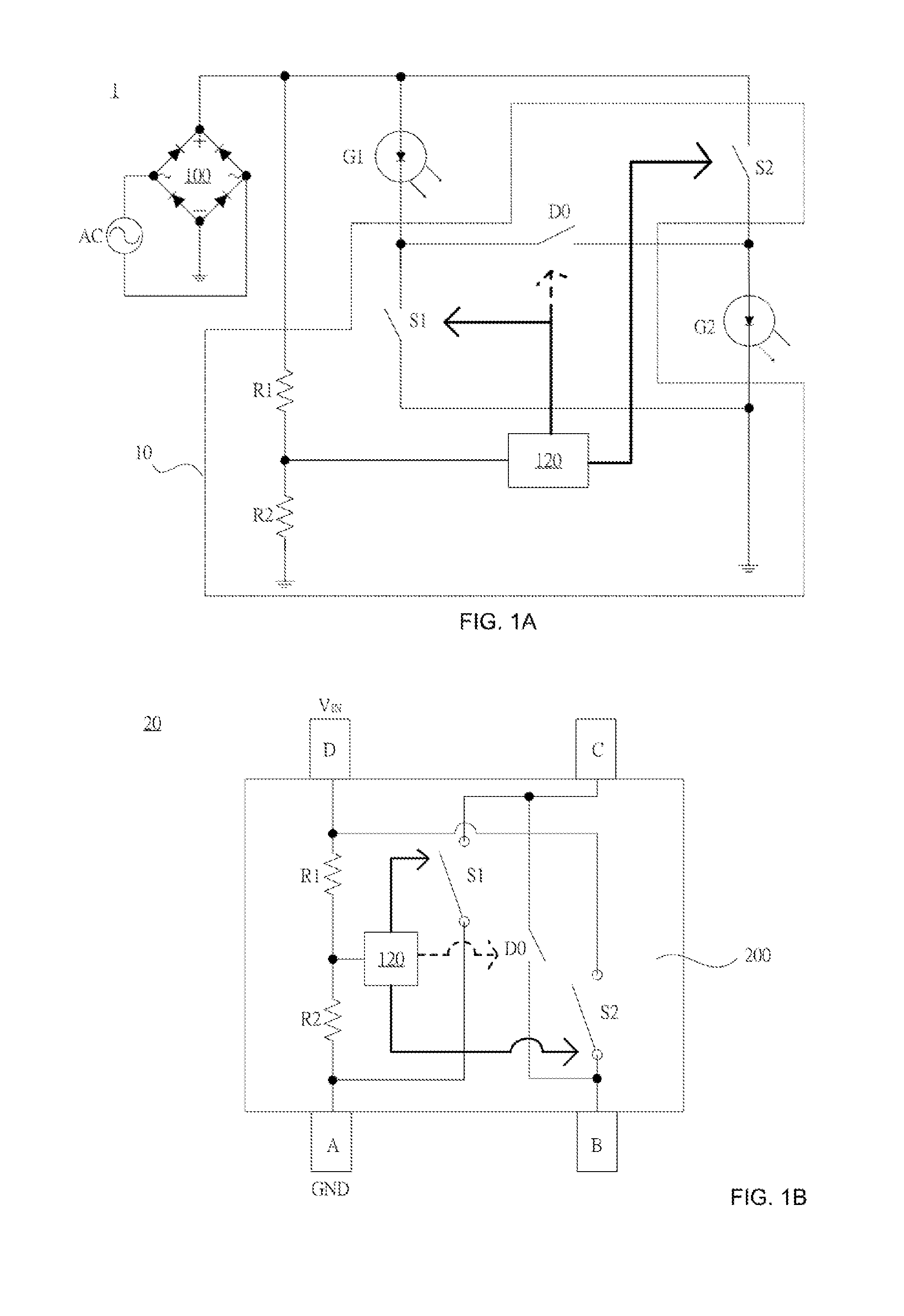
[0025]FIG. 1A illustrates a block diagram of an illuminating apparatus powered by a single AC voltage source and having a control circuit according to the embodiment of the present invention. The illuminating apparatus 1 comprises a single AC voltage source, a rectifier 100, a first extrinsic LED array G1, a second extrinsic LED array G2, and a control circuit 10 used for auto-configuring the two extrinsic LED arrays. The control circuit 10 comprises a voltage divider (resistors R1 and R2), a first switch S1, a second switch S2, a freewheeling switch D0, and a switch controller120. The first extrinsic LED array G1 and the second extrinsic LED array G2 each comprise an LED array in any form. Besides, each of the two extrinsic LED arrays has at least...


PUM


Abstract

Disclosed are control circuits capable of auto-configuring two LED arrays either in parallel when the two LED arrays are operating off of 100±20% V AC voltage sources or in series when the two LED arrays are operating off of 200±20% V AC voltage sources according to the detection of the AC input voltage magnitude. The disclosed control circuits, ruling over the parallel or series configuration of the two LED arrays, could be implemented in discrete forms or as integrated circuits (IC).

Description

CROSS-REFERENCE TO RELATED APPLICATIONS[0001]This application claims the benefits of TW102145706, filed Dec. 11, 2013, and TW103131204, filed Sep. 10, 2014, the disclosures of which are fully incorporated herein by reference.BACKGROUND OF THE INVENTION[0002]1. Field of the Invention[0003]The present invention relates to control circuits able to auto-configure two extrinsic LED arrays either in parallel or in series in accordance with the detection result of the AC input voltage range. The LED illuminating apparatuses auto-configured with the aid of disclosed control circuits could support dual-range (both 100±20% V and 200±20% V) operation, enabling a wider range of acceptable AC input.[0004]2. Description of the Prior Art[0005]As compared with the traditional lighting devices, the LED has a higher luminous efficacy. The LEDs can give off more than 100 lumens per watt because less electric energy is converted into waste heat. In sharp contrast, a traditional bulb only gives off abou...

Claims


Application Information

Patent Timeline
IPC IPC(8): H05B33/08H05B44/00
CPCH05B33/0806H05B45/395Y02B20/30
Inventor YU, CHING SHENGWANG, CHIH LIANGCHEN, KUANG HUI
Owner GRP TECH
Why Eureka
Try Eureka