LED light control assembly and system

a technology of led light and assembly, applied in the direction of electric variable regulation, process and machine control, instruments, etc., can solve the problem that the unaided eyes of individuals cannot observe the light signals of individuals

Active Publication Date: 2015-06-11
FEDERAL LAW ENFORCEMENT DEV SERVICES
View PDF4 Cites 47 Cited by
  • Summary
  • Abstract
  • Description
  • Claims
  • Application Information

AI Technical Summary

Problems solved by technology

The light signals are not observable to the unaided eyes of an individual.
It is commonly known that the last mile of most sy

Method used


Image

  • LED light control assembly and system
  • LED light control assembly and system
  • LED light control assembly and system

Examples


Embodiment Construction

[0067]While this invention may be embodied in many different forms, there are described in detail herein specific alternative embodiments of the invention. This description is an exemplification of the principles of the invention and is not intended to limit the invention to the particular embodiments illustrated. For the purposes of this disclosure, like reference numerals in the figures shall refer to like features unless otherwise indicated.

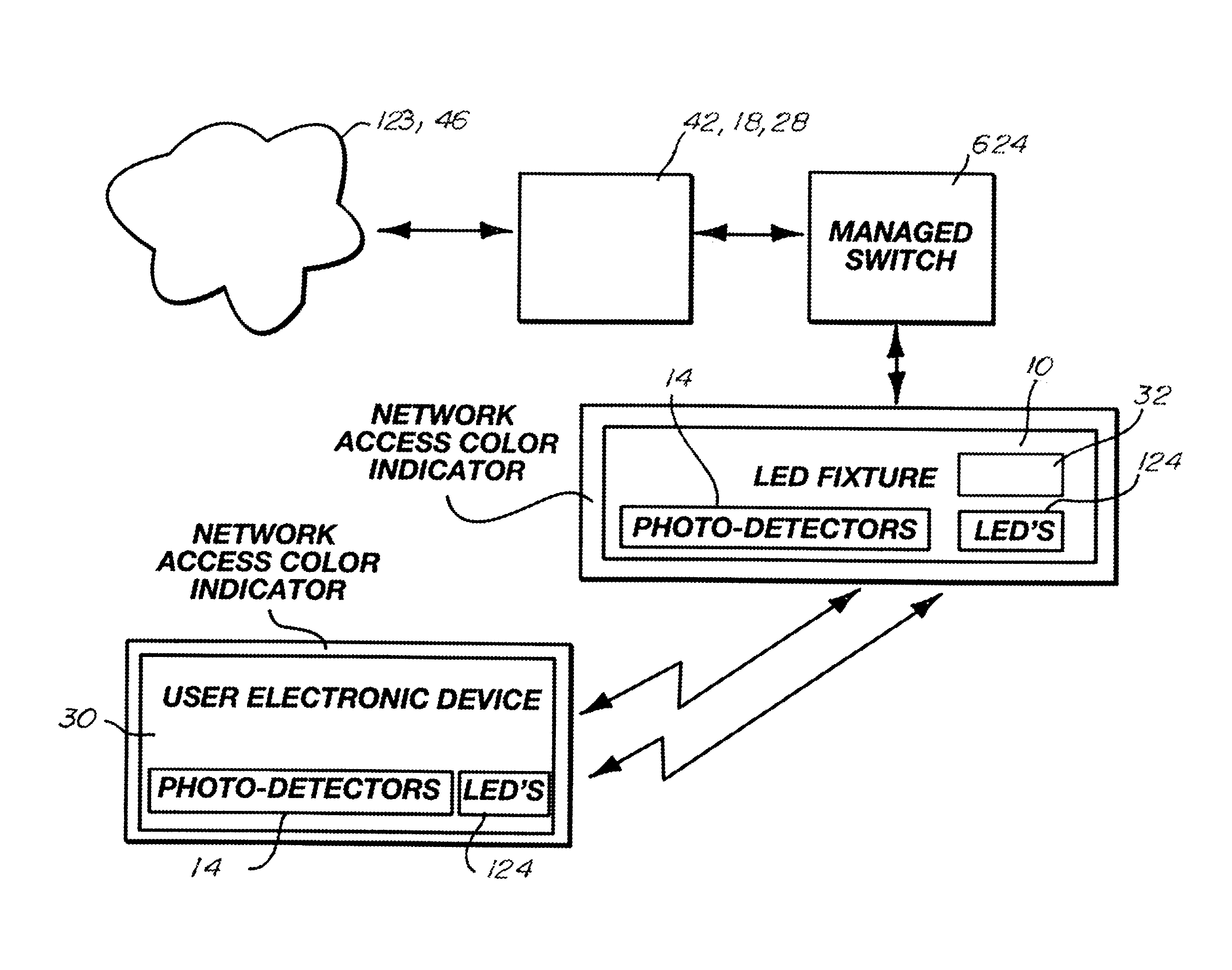
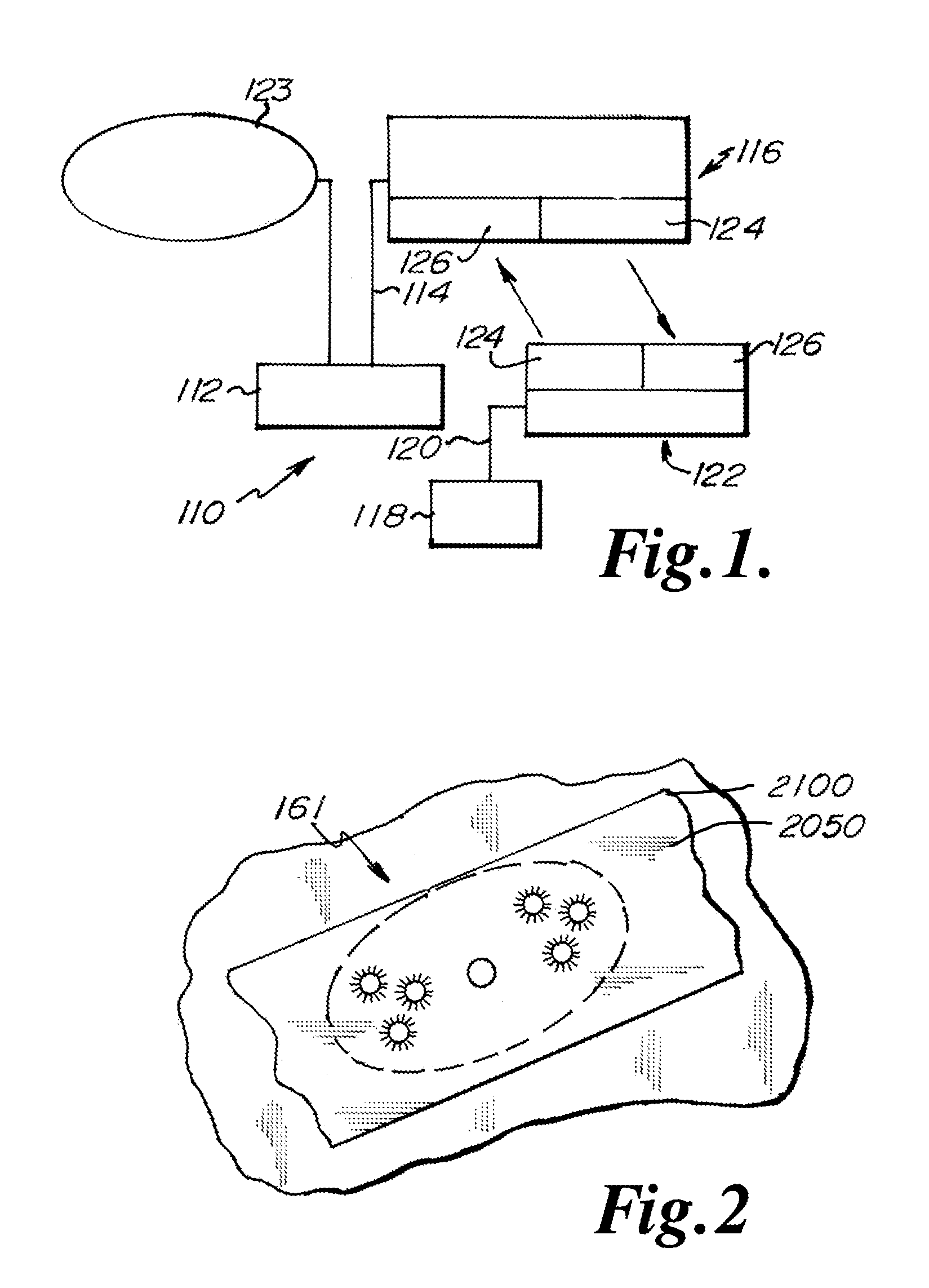
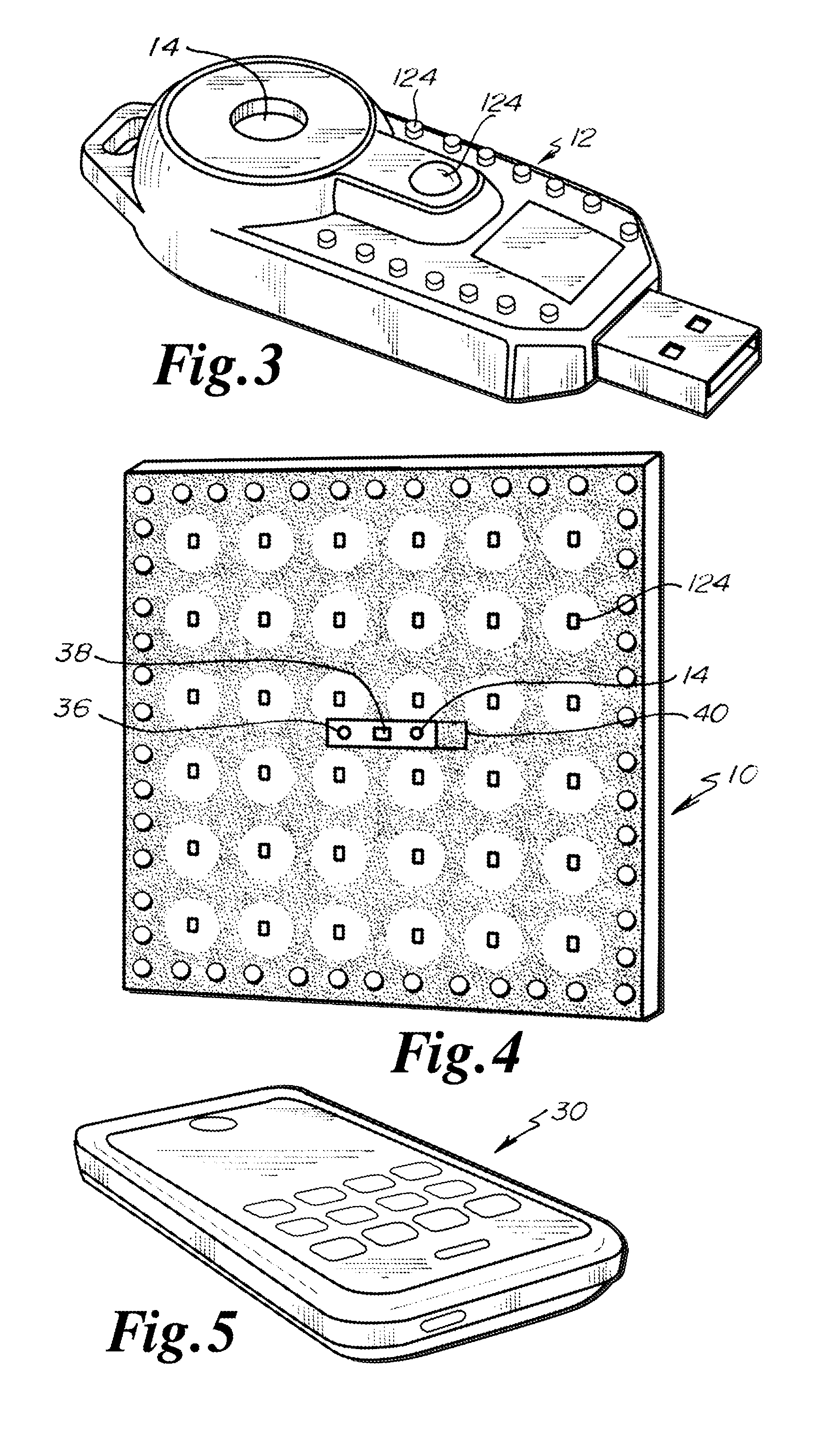
[0068]In each of the embodiments discussed below, the LEDs 124, 2100 may be formed of the same or different colors. The LED's 124, 2100 are in communication with a controller 20 which may be configured to select the color of the LEDs 124, 2100 to be illuminated forming the light signal.

[0069]It should be noted that in some embodiments, the LED's 124, 2100 can both emit and receive light. In such an embodiment, the LED's 124, 2100 can act both as a transmitter or receiver. More information on such bi-directional LEDs can be found in U.S. Pat. N...


PUM


Abstract

An LED light and communication system is in communication with a broadband over power line communications system. The LED light and communication system includes at least one optical transceiver light fixture. The optical transceiver light fixture includes a plurality of light emitting diodes, at least one photodetector, and a processor. A facility control unit is in communication with the light emitting diode light fixtures and a control server. The facility control unit is constructed and arranged to control the operation of the optical transceiver light fixtures.

Description

CROSS-REFERENCE TO RELATED APPLICATIONS[0001]This application claims priority to Provisional Application No. 61 / 927,638, filed Jan. 15, 2014, the disclosure of which is expressly incorporated herein by reference.[0002]This application is also a continuation-in-part of U.S. patent application Ser. No. 14 / 208,125 filed on Mar. 13, 2014 which claims benefit of 61 / 778,672, filed Mar. 13, 2013 and is a continuation-in-part of U.S. patent application Ser. No. 13 / 427,358, filed Mar. 22, 2012, now U.S. Pat. No. 8,744,267 which is a continuation of U.S. patent application Ser. No. 12 / 126,342 filed May 23, 2008 now abandoned which claimed priority to U.S. Provisional Patent Application Ser. No. 60 / 931,611 filed May 24, 2007 the disclosures all of which are expressly incorporated by reference herein in their entireties.[0003]This application is a continuation-in-part of U.S. patent application Ser. No. 14 / 270,670 filed May 6, 2014 which claims benefit of 61 / 819,861 filed May 6, 2013, the discl...

Claims


Application Information

Patent Timeline
IPC IPC(8): H05B33/08H05B44/00
CPCH05B33/0854H05B33/0869H05B33/0863H04B10/1143H04B10/1149H04B10/116H05B45/22H05B45/20H05B47/12H05B47/11Y02B20/40H05B47/195H05B47/125
Inventor PEDERSON, JOHN C.
Owner FEDERAL LAW ENFORCEMENT DEV SERVICES
Why Eureka
Try Eureka