
Independent drive motors for machinery positioning apparatus having independent lifting motors

Active Publication Date: 2015-06-18
MACTON CORP +1
View PDF57 Cites 11 Cited by
  • Summary
  • Abstract
  • Description
  • Claims
  • Application Information

AI Technical Summary

Benefits of technology

The lifting and positioning apparatus of this patent allows for more accurate and precise positioning, provides load balancing, and increases safety and reliability. It also prevents damage to the support structure, allows for easier repair and replacement of critical wear parts, and saves time in replacing columns and drive parts. The apparatus includes interchangeable columns, a flexible drive system, and self-contained motor and sensor packages.

Problems solved by technology

This allows for one column to be removed with limited repair skill or specialized mechanical knowledge.
In comparison to the prior art, this saves a great deal of time.

Method used


Image

  • Independent drive motors for machinery positioning apparatus having independent lifting motors
  • Independent drive motors for machinery positioning apparatus having independent lifting motors
  • Independent drive motors for machinery positioning apparatus having independent lifting motors

Examples


Embodiment Construction

[0046]Referring now to the drawings, wherein like reference numerals designate corresponding structure throughout the views.

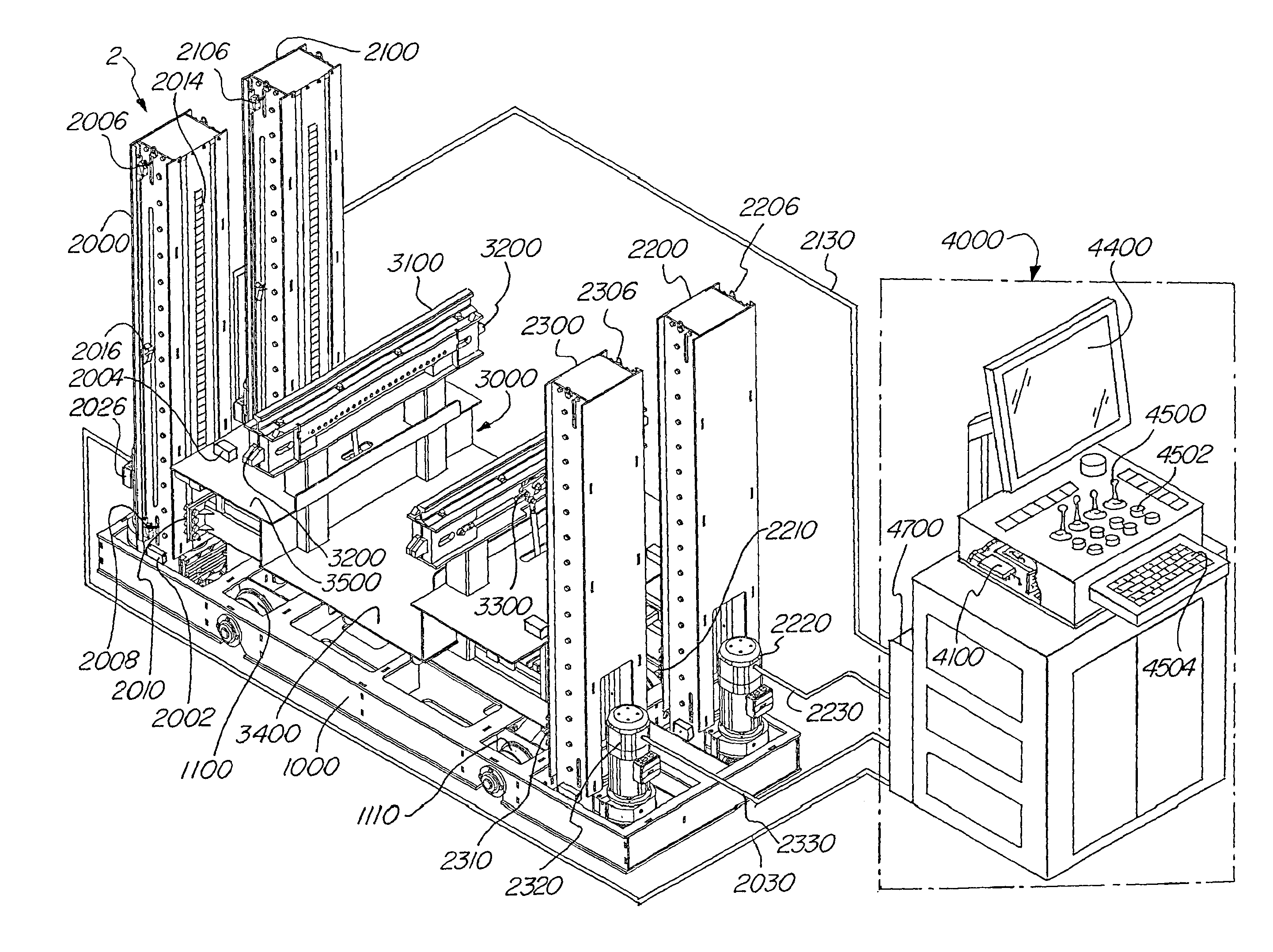
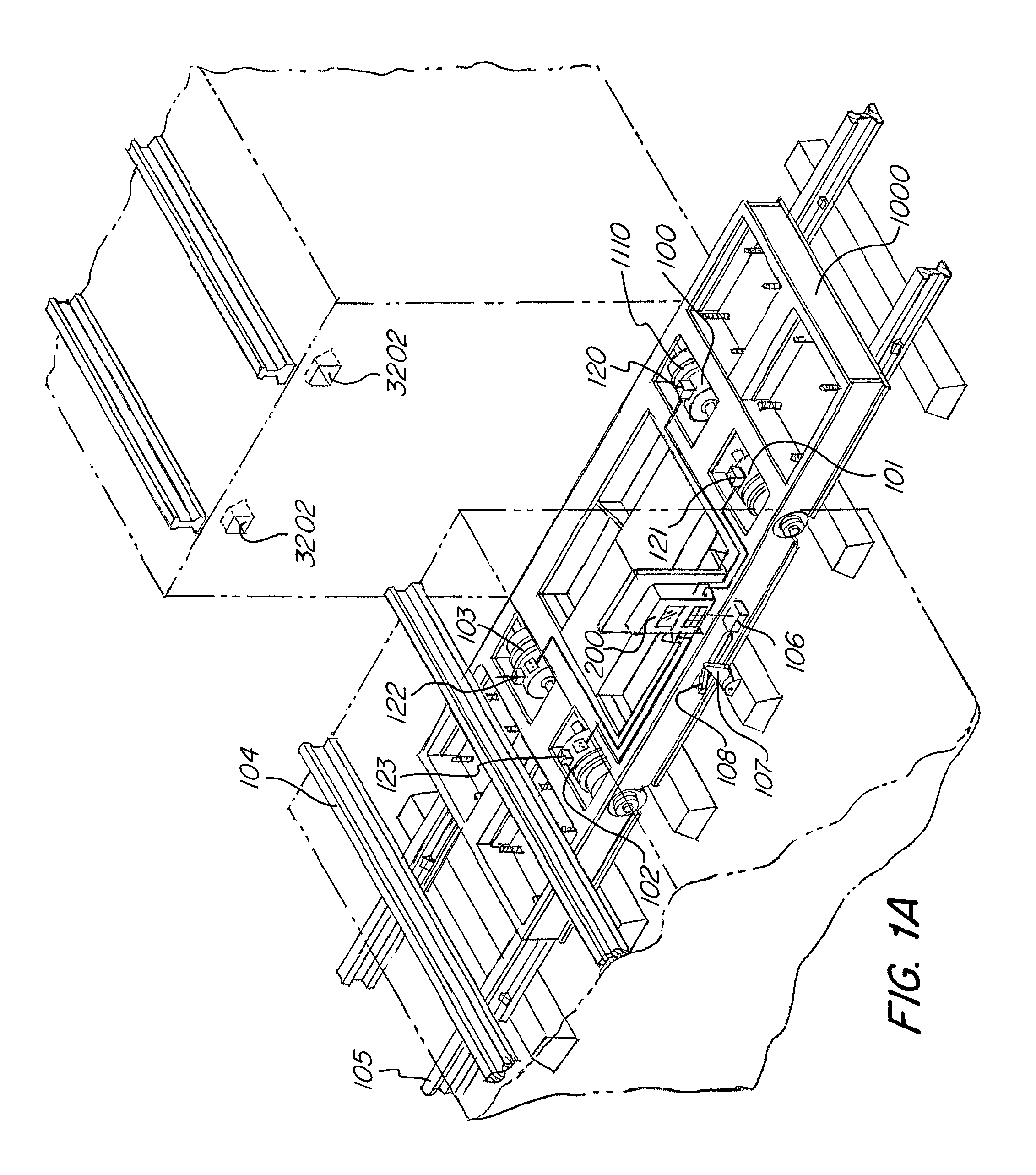
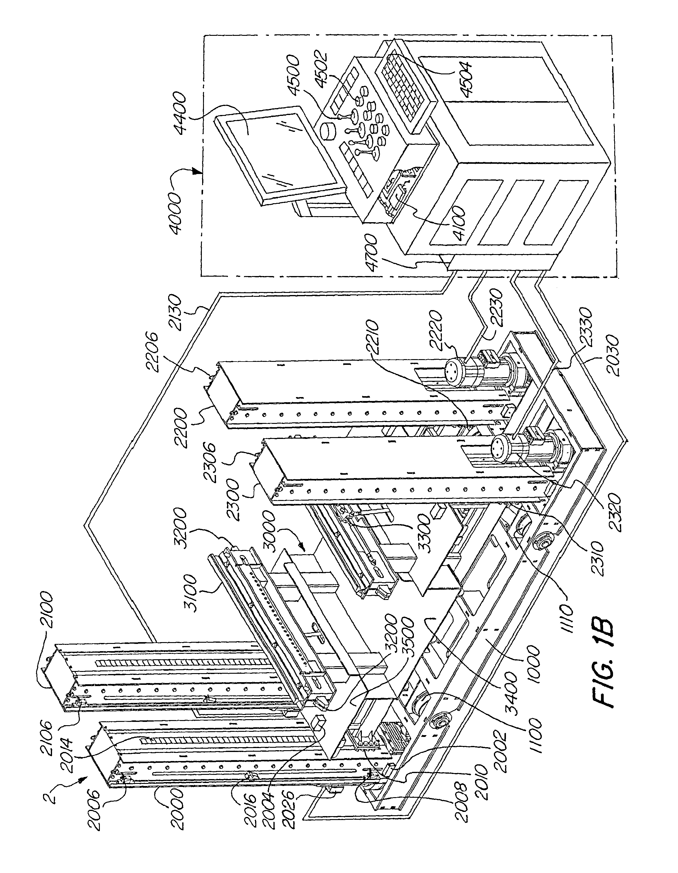
[0047]FIG. 1A shows base 1000 with lifting columns (2020, 2120, 2220, 2320) removed. Drive motors 100, 101, 102, 103 are connected to wheels 1110. The connection between wheels 1110 and the drive motors may include a gearing system, but may also be direct drive. Drive motors include a sensor array 120, 121, 122, 123, which may include position and / or load sensors. For example, a rotational encoder type sensor may monitor position. Load sensors may include electrical load sensors, torque sensors, mechanical load sensors such as strain / force sensors and the like. The motors are connected to a controller 200. Optionally, the drive controller 200 may be connected to controller 4000 or drive controller 200 may be absent and drive motors 100, 101, 102, 103 may be connected directly to controller 4000. It is contemplated that the functions of a controller as shown and...


PUM


Abstract

A lifting apparatus and controller therefore, where the lifting apparatus includes independently driven lifting columns and independently driven wheels that are controlled by a controller having a number of sensors such as limit sensors, position sensors, rotation sensors, laser sensors, torque sensors and the like. The independent motors for lifting and driving may also be removed easily to provide for improved servicing and maintenance. The various sensor signals are used to calculate, coordinate and calibrate the apparatus for precise and safe movement by the motors in order to perform lifting and positioning operations, for example rail car repair and service.

Description

FIELD OF THE INVENTION[0001]The following invention relates to a lifting and positioning apparatus. More particularly, the following relates to lifting machinery and a controller for rail car and engine maintenance having independent drive and lifting motors.BACKGROUND OF THE INVENTION[0002]In many factories and repair shops, lifting and positioning equipment is used to move heavy objects or to remove parts to expose the underside of the vehicle or to provide easier access for repair and / or replacement of parts and assemblies. This allows a worker to inspect, repair or assemble various items with greater ease than when attempting to work through gaps or crawl spaces.[0003]U.S. Pat. No. 7,603,734 to Connelly et al discloses a system for lifting a passenger boarding bridge for an aircraft that avoids rack fault. The system has two electromechanical screw jacks. Each motor receives a signal for adjusting the height of the tunnel selection and the system uses rotational sensors to monit...

Claims


Application Information

Patent Timeline
IPC IPC(8): B66F9/075B66F3/44B66F7/12
CPCB66F9/07577B66F3/44B66F7/12B66F7/28B66F7/025B66F1/06B66F7/02
Inventor KNAPP, RYAN W.MCGONAGLE, PETERO'DONNELL, MARK
Owner MACTON CORP
Learn More