Unlock instant, AI-driven research and patent intelligence for your innovation.

Electromagnetically actuated coupler

a technology of electric actuation and coupler, which is applied in the direction of mechanical actuation clutches, interlocking clutches, transportation and packaging, etc., can solve problems such as energy loss, and achieve the effect of reducing the stroke of locking mechanism and accelerating engagemen

Active Publication Date: 2015-06-18
FORD GLOBAL TECH LLC
View PDF9 Cites 2 Cited by
  • Summary
  • Abstract
  • Description
  • Claims
  • Application Information

AI Technical Summary

Benefits of technology

The patent describes a wheel end assembly that includes a first shaft, a second shaft, a coil, and a collar. The collar can rotate relative to the second shaft and has clutch teeth that engage or disengage with the first shaft based on an electromagnetic field produced by the coil. This design allows for quicker engagement and reduces the stroke of the locking mechanism compared to traditional spline coupling devices. The technical effect of this invention is improved performance and efficiency of the wheel end assembly.

Problems solved by technology

This continuous rotation of the halfshafts produces energy losses associated with the rotating mass of the halfshafts and other RDU components including parasitic pumping losses from the internal components of the RDU.

Method used


Image

  • Electromagnetically actuated coupler
  • Electromagnetically actuated coupler
  • Electromagnetically actuated coupler

Examples


Embodiment Construction

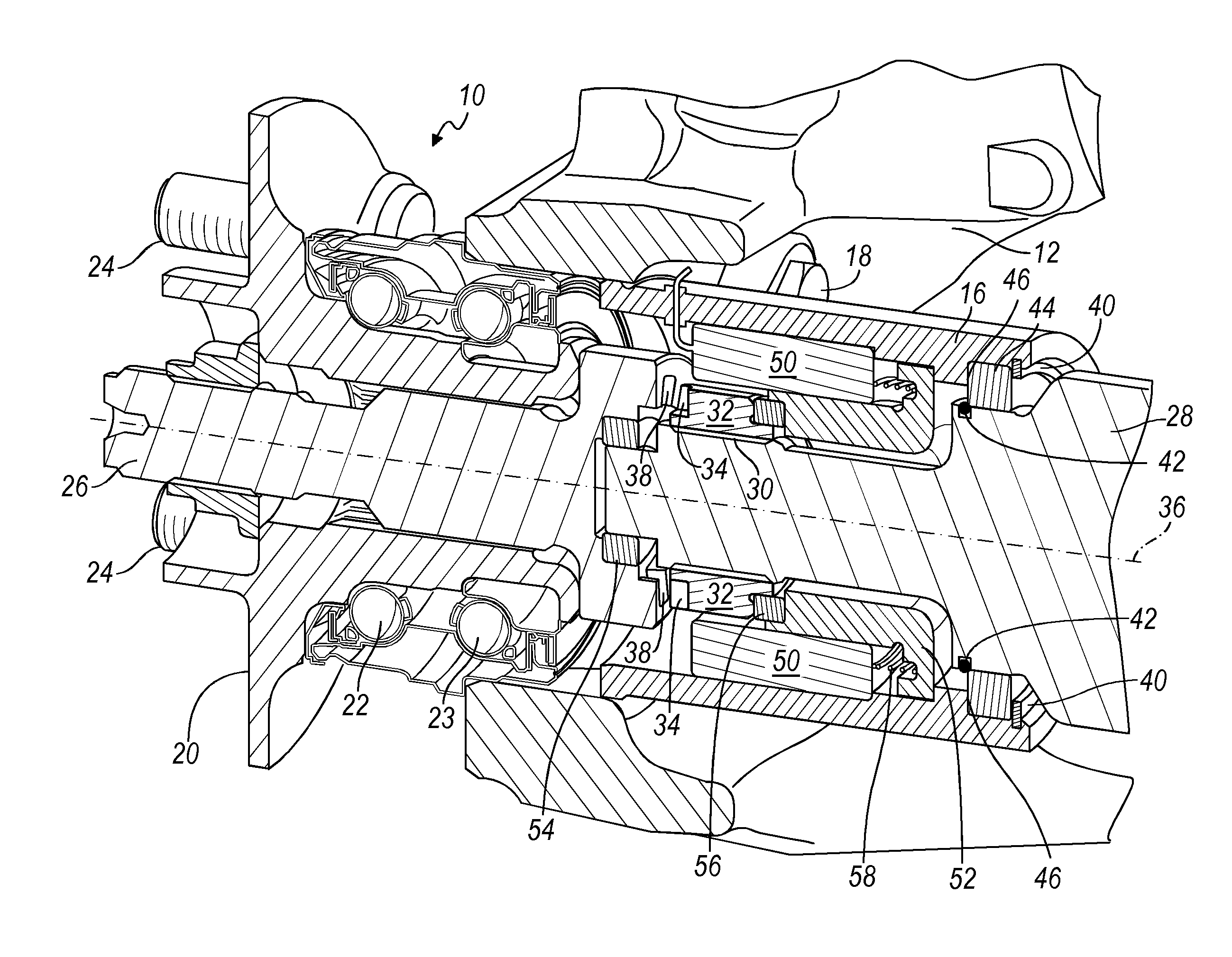
[0013]FIGS. 1 and 2 show a wheel end assembly 10 including a wheel end knuckle 12, which is secured to a vehicle frame; a halfshaft 14, which extends outboard and leftward for a RDU and its differential mechanism; an inner hub housing 16, which is secured by bolts 18 to knuckle 12; and a wheel hub 20, which is supported by wheel bearings 22, 23 on knuckle 12 and carries lug bolts 24. Although components for the left hand side of the vehicle are shown, there is a disconnect at both the left and right wheel ends, with the right hand side being symmetrical with the left hand side.

[0014]As FIG. 2 shows, the wheel end axle shaft comprises an outboard shaft 26, rotationally fixed to the wheel hub 20, and an inboard shaft 28, secured to halfshaft 14 and free to rotate within the inner hub housing 16. The inboard shaft 28 has provisions for a CV joint on the inboard side of the shaft and is formed with external, axial spline teeth 30.

[0015]A sliding collar 32 is secured to the inboard shaft...


PUM


Abstract

A wheel end assembly includes a first shaft supported on a knuckle secured to a vehicle frame, including first clutch teeth, a second shaft secured to the halfshaft, a coil, and a collar rotatably secured to the second shaft, axially displaceable relative to the first shaft, including second clutch teeth that alternately engage the first clutch teeth due to an electromagnetic field produced by energizing the coil and disengage from the first clutch teeth.

Description

BACKGROUND OF INVENTION[0001]This invention relates generally to a driven axle of a motor vehicle and more particularly to an electrically actuated clutch or coupler for disconnecting a drive connection to the wheels when torque is not needed at the axle.[0002]Halfshafts that extend laterally from rear axle drive units (RDU's) of front engine transversely-mounted all wheel drive (AWD) vehicles, continuously rotate with the rear wheels even when torque is not being transmitted to the RDU.[0003]This continuous rotation of the halfshafts produces energy losses associated with the rotating mass of the halfshafts and other RDU components including parasitic pumping losses from the internal components of the RDU.[0004]A need exists in the industry to disconnect the rear wheels from the RDU when torque is not needed at the rear axle whereby improved fuel economy of the vehicle can be realized.SUMMARY OF INVENTION[0005]A wheel end assembly includes a first shaft supported on a knuckle secur...

Claims


Application Information

Patent Timeline
Patent Type & Authority Applications(United States)
IPC IPC(8): F16D27/09B60K23/08F16D11/14
CPCF16D27/09B60K23/08F16D11/14B60K17/35B60K2023/0858F16D27/108F16D27/118
Inventor SAIEG, JOHN R.POVIRK, JACOB M.ISKEN, II, DENNIS W.ANDONIAN, BRIAN J.
Owner FORD GLOBAL TECH LLC
Features
  • R&D
  • Intellectual Property
  • Life Sciences
  • Materials
  • Tech Scout
  • Unparalleled Data Quality
  • Higher Quality Content
  • 60% Fewer Hallucinations
Learn More