Linear damper

Inactive Publication Date: 2015-06-18
CHI HUA FITNESS
View PDF3 Cites 17 Cited by
  • Summary
  • Abstract
  • Description
  • Claims
  • Application Information

AI Technical Summary

Benefits of technology

[0018]Based on the features disclosed, the linear displacement motion of the driving rod is converted into the circular rotation motion of the permanent magnet, and the Eddy load is formed between the permanent magnet and magnetic surface to produce torque in order to replace the magnetic reluctance by the conventional hydraulic oil for solving oil leakage problem and ensuring the

Problems solved by technology

The piston rod 134 of the conventional hydraulic damping device 13 with a back and forward motion has frequent friction with an oil seal 136, resulting oil leakage problem fouling ground and equipment, and affecting the damping function.
Moreover, after a period of using the hydraulic oil, the viscosity of the hydraulic oil will change

Method used


Image

  • Linear damper
  • Linear damper
  • Linear damper

Examples


Embodiment Construction

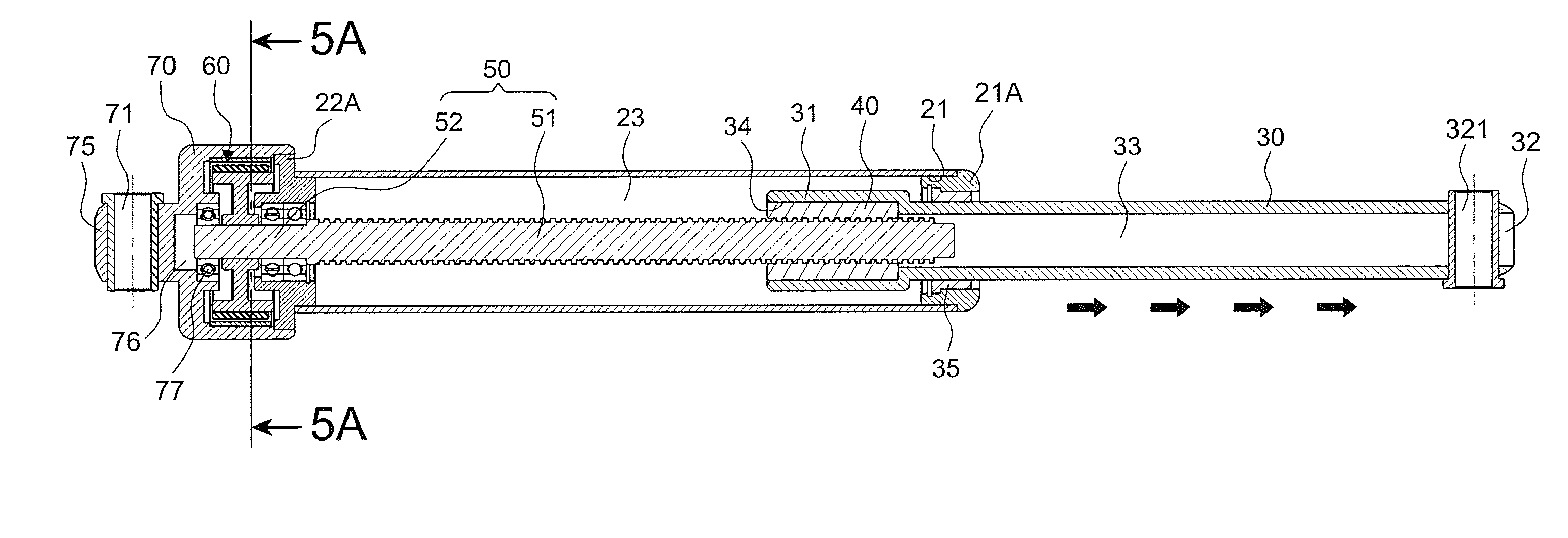
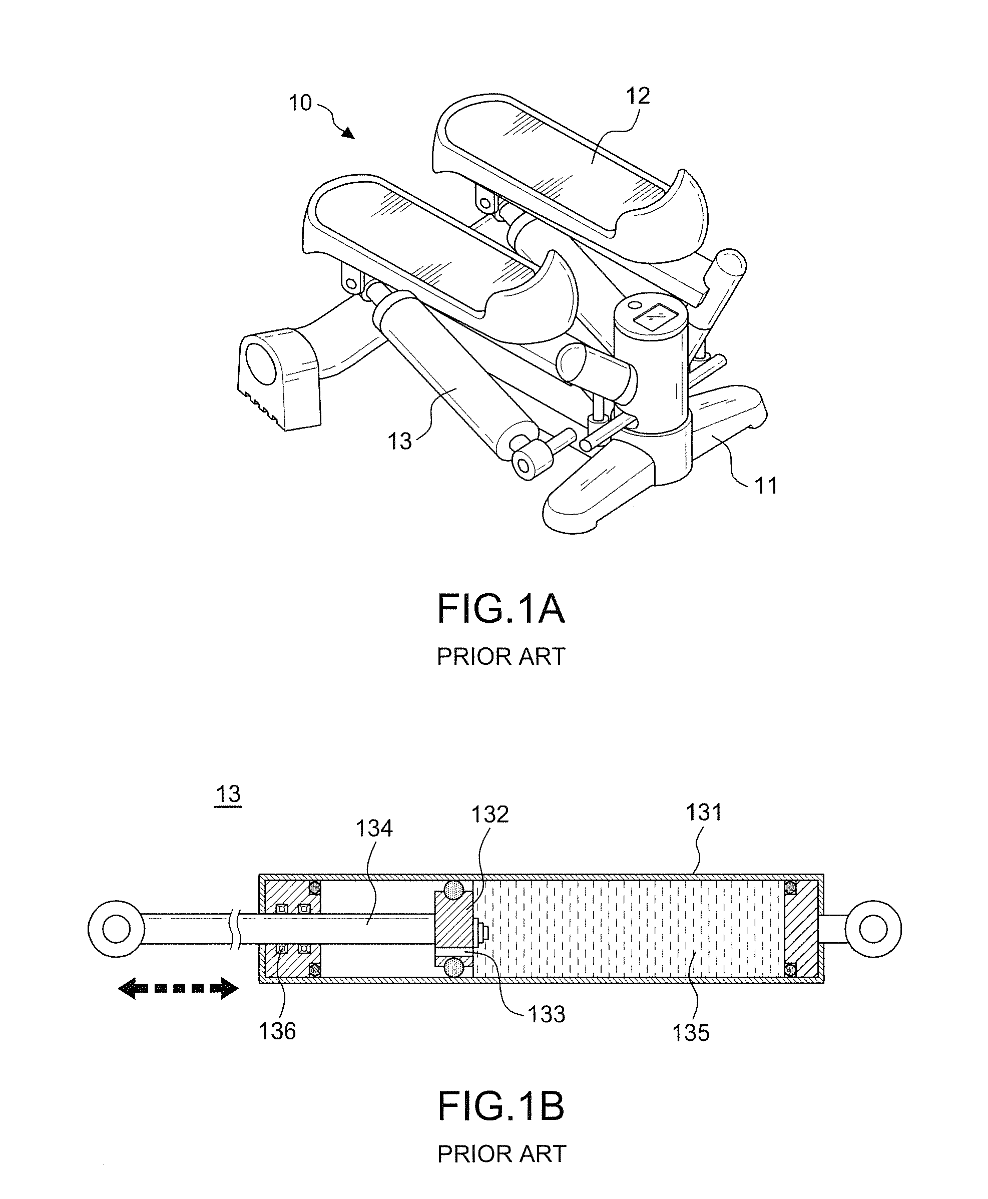
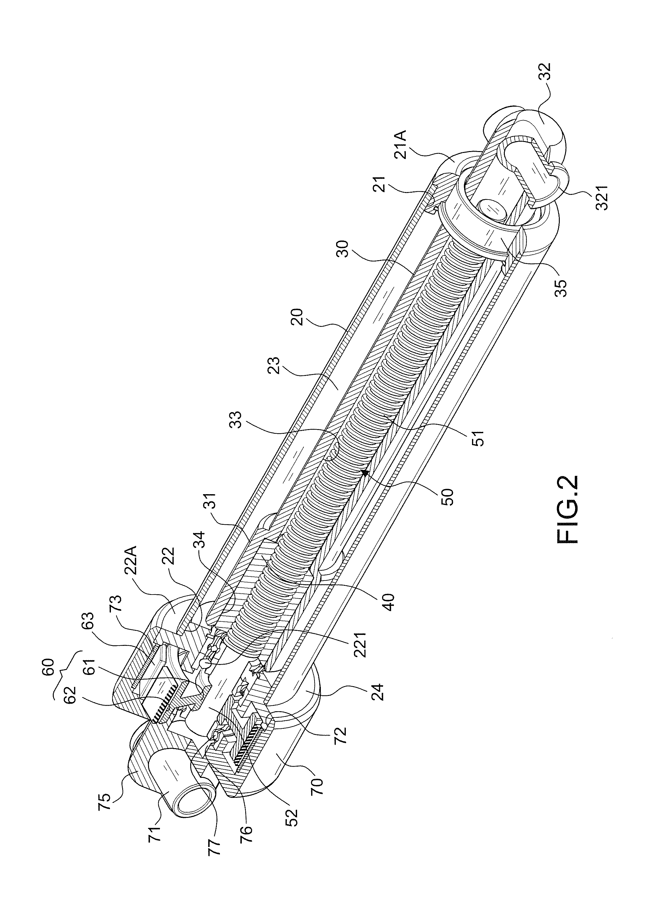
[0028]Referring to FIGS. 2 through 5, the preferred embodiment of a linear damper in accordance with the present invention comprises a tube body 20 respectively having a first through hole 21 and a second through hole 22 at both ends, and a first axial passage 23 formed between the first through hole and second through hole 21, 22; a driving rod 30 having an inner side end 31 and an outer side end 32, the outer side end 32 projecting outside the first trough hole 21 and having a first pivot portion 321, and the inner side end 31 being movable in the tube body 20. The structure disclosed above is prior art and thus will not be described in details here.

[0029]The present invention is characterized in that the second through hole 22 of the tube body 20 has a first bearing 221 at an inner periphery thereof; in the embodiment, the first through hole 21 of the tube body 20 further includes a first axial sleeve 21A nested in an outer port of the tube body 20, and a bush 35 is arranged betw...


PUM


Abstract

A linear damper, particularly to convert the linear displacement motion into the circular rotation motion for getting magnetic reluctance, comprising: a tube body and a driving rod being movable in the tube body; wherein the driving rod in the first axial passage is in the linear displacement motion, and the screw rod is rotated by the screw sleeve to drive the fixed seat for rotation, so that the permanent magnet is in a circular rotation motion; a torque is produced by Eddy load formed between the permanent magnet and the magnetic surface to be as a buffering and damping of the linear displacement motion of the driving rod, solving oil leakage problem and ensuring the service life and quality.

Description

BACKGROUND OF THE INVENTION[0001]1. Field of the Invention[0002]The invention relates to a linear damper, particularly to a non-hydraulic damper being able to convert the linear displacement motion into the circular rotation motion for getting magnetic reluctance.[0003]2. Description of the Related Art[0004]In Indoor sports or rehabilitation equipment, some actuating mechanism must be set for the load device or damping device, such as rowing fitness, strength training machines, and etc. A foot sports equipment 10 as show in FIG. 1A has a seat 11, two pedals 12 arranged on the seat 11 for stepping thereon, and a damping device 13 respectively connected between two pedals 12 and the seat 11. The indoor sports equipment is limited to space, so the damping device 13 is mostly used in the hydraulic cylinder as shown in FIG. 1B.[0005]This type of hydraulic cylinder generally includes: a cylinder 131, a piston 132 installed in the cylinder 131, and having a passage 133 thereon and a piston...

Claims


Application Information

Patent Timeline
IPC IPC(8): F16F6/00
CPCF16F6/005F16F15/035
Inventor LEE, YING-CHE
Owner CHI HUA FITNESS
Why Eureka
Try Eureka