

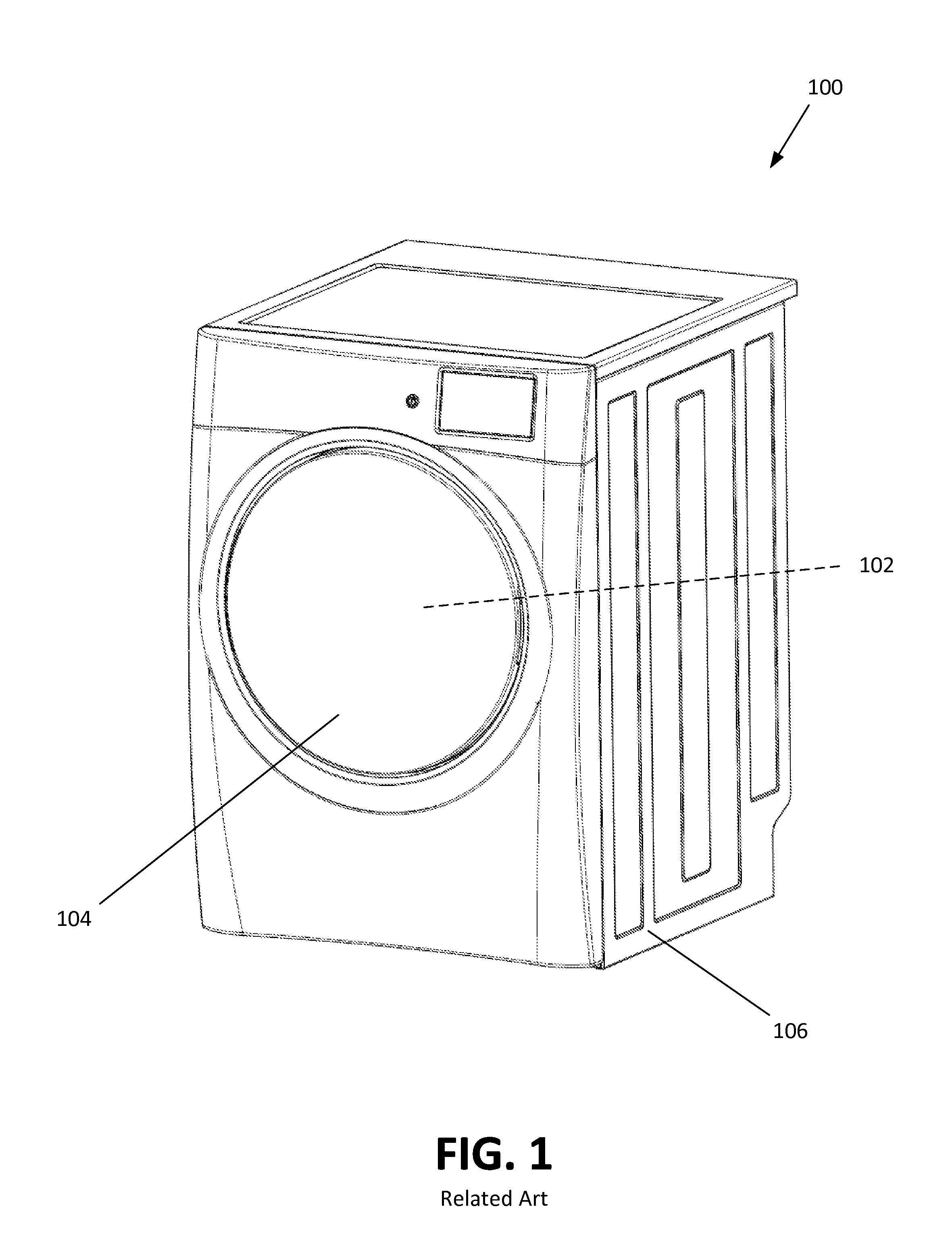
Laundry dryer with emergency closing ventilation system
a ventilation system and laundry dryer technology, applied in the field of laundry dryers, can solve the problems of slow detection and/or response to fire, system may add considerable expense and complexity to the appliance, and become more and more restrictive, so as to restrict airflow and restrict airflow
- Summary
- Abstract
- Description
- Claims
- Application Information
AI Technical Summary
Benefits of technology
Problems solved by technology
Method used
Image

Examples
Embodiment Construction
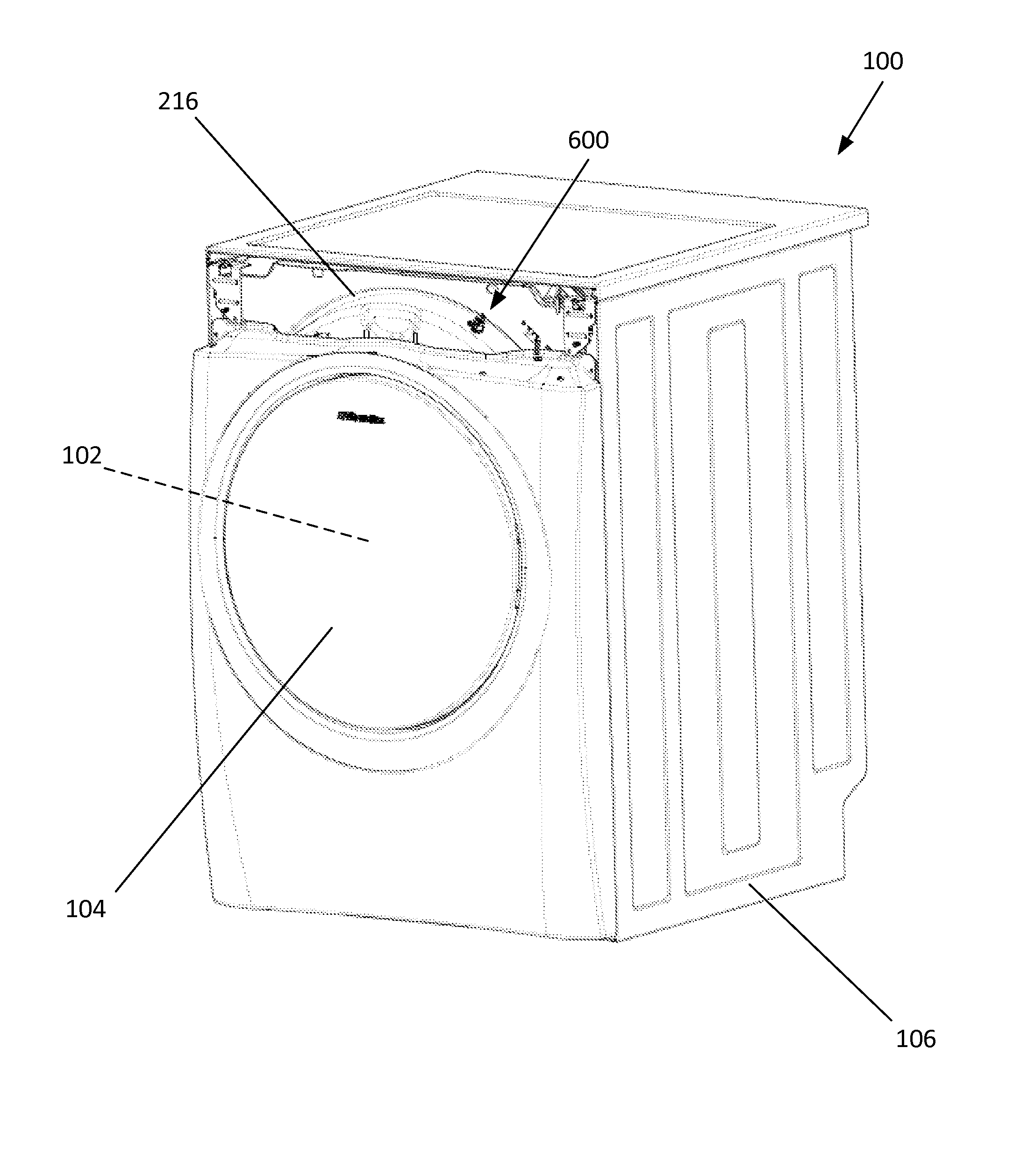
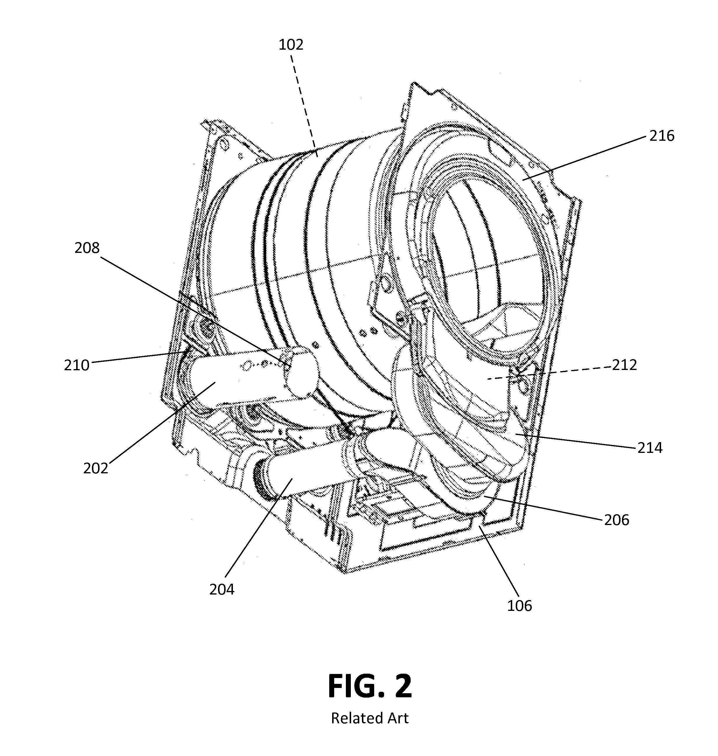
[0031]Referring to FIGS. 6-15, a tumble dryer 100 is equipped with an air closure system configured to suppress and / or conceal an internal fire within tumble dryer 100. As depicted in FIGS. 6-15, the tumble dryer 100 is a vented tumble dryer configured to exhaust at least a portion of air leaving a drying chamber 102 to an outside of the vented laundry dryer. In other suitable embodiments, the tumble dryer 100 may recirculate the entire process air which passes through the drying chamber 102 without exhausting any portion thereof. The air closure system may comprise a sensor 600 (e.g., a thermostat, smoke detector, or the like) disposed in a bulkhead 216 of the drying chamber 102 of the tumble dryer 100, and an air closure assembly 1000 (FIGS. 10-15) coupled to the ventilation system of the tumble dryer 100. In the embodiment depicted in FIG. 6, sensor 600 is disposed near the top of bulkhead 216, but, in other embodiments, sensor 600 may be disposed at other locations around the ci...
PUM
 Abstract
Description
Claims
Application Information