Autonomous device for advanced image analysis, intelligent image recognition and image evaluation

Inactive Publication Date: 2021-01-21
SANEZOO SE
View PDF0 Cites 1 Cited by
  • Summary
  • Abstract
  • Description
  • Claims
  • Application Information

AI Technical Summary

Benefits of technology

[0028]Furthermore, the essence of the invention is that the camera and process blocks housings are made of a thermally conductive material, for example aluminium. These housings may be provided with ribbing to improve heat dissipation to the surroundings. The camera block cover may be made of metal or plastic, for example polyetheretherketone, ABS, or PVC, which is preferable if the camera module has to be thermally insulated from the camera block housing. The process block cover can also be made of metal or plastic, for example polyetheretherketone, which is preferable if it is necessary to provide permeability for Wi-Fi, Bluetooth, and the like.
[0029]Another advantage of the invention is that the camera block housing has a reinforced wall for effectively dissipating heat from the camera block. The location and design requirements of the reinforced wall are based on the design of the camera module used.
[0030]It is preferred that the camera block or process block is provided with at least one heat pump. The heat pump maintains the optimum temperature of the camera module or internal parts of the process block, thereby reducing the thermal stress of the camera module and the internal parts of the process block. Reducing thermal stress results in longer life and reliability of individual components. By keeping the temperature of the camera module in the optimum range, the image noise reduction in the image is also achieved, even at high computing unit load or when using an autonomous device in a space with a higher ambient temperature.
[0031]The term “heat pump” refers to any technical device that enables the temperature control of

Problems solved by technology

This results in a reduction in the temperature of the camera block and thus in

Method used


Image

  • Autonomous device for advanced image analysis, intelligent image recognition and image evaluation
  • Autonomous device for advanced image analysis, intelligent image recognition and image evaluation
  • Autonomous device for advanced image analysis, intelligent image recognition and image evaluation

Examples


Embodiment Construction

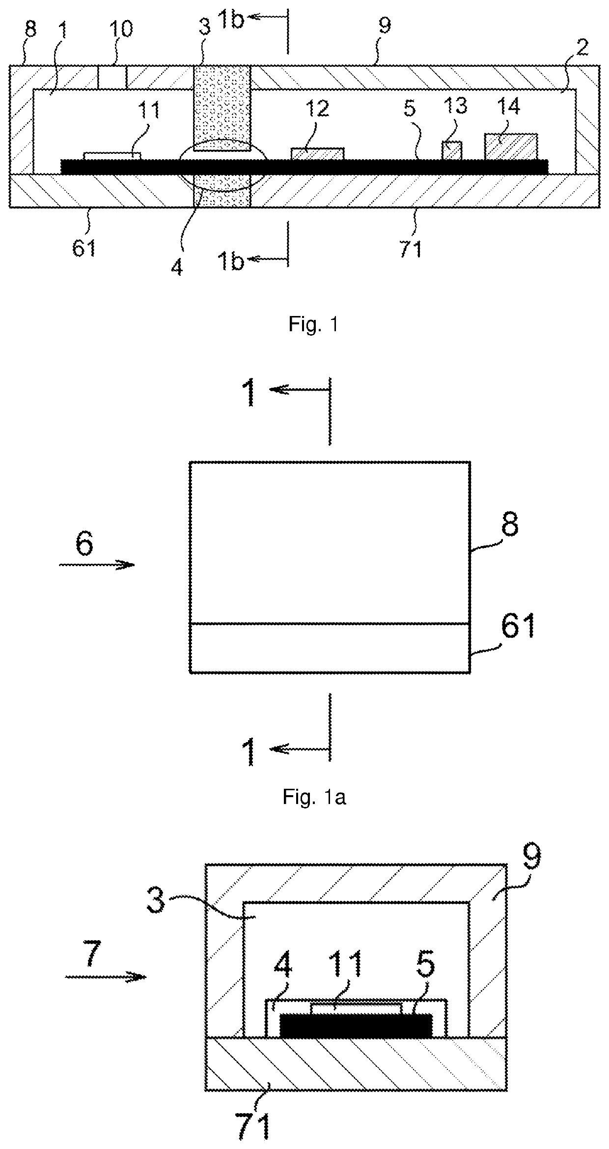
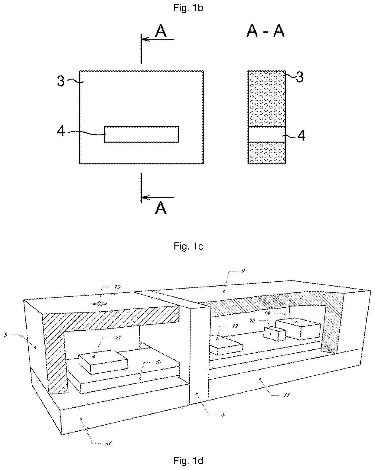
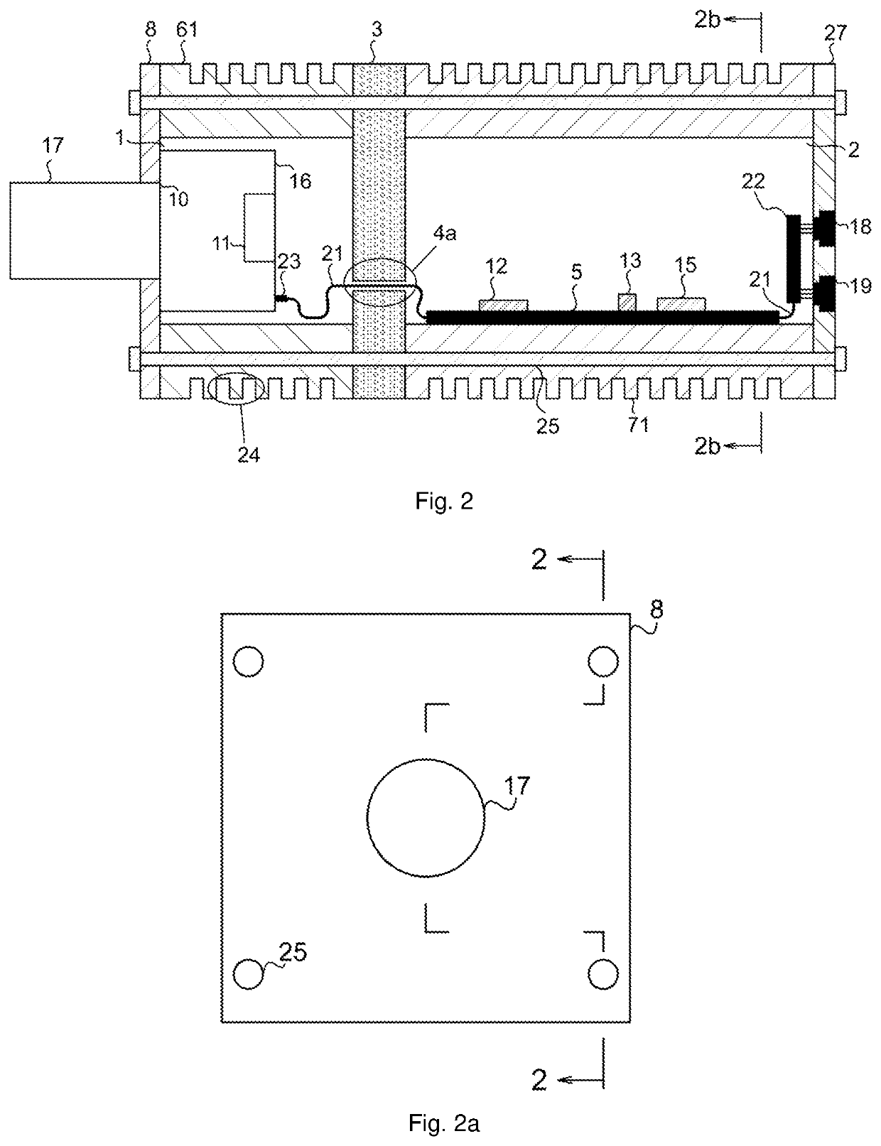
[0055]The invention will be explained in more detail by way of example with reference to the corresponding drawings. In the drawings and figures, the solution is shown in an exemplary embodiment, which is not limiting to other variations of the present summary of the invention, or to variants that are apparent to one skilled in the art.

[0056]For a description of the function of an autonomous device (AD), the following definitions are used, which will be further used in the description below.

Detecting device with an image sensor—is a device for image digital signal acquisition. It includes not only classic cameras and raster scan camera modules, but also line cameras, 3D cameras, cameras with spectral and hyperspectral sensors, thermocameras, X-ray sensors and other devices with sensors producing digital signal.

Camera Block—is a part of AD that acts as a digital camera and is a source of image signal for AD.

Interface Unit—is a set of electronic technical means allowing the connection...


PUM


Abstract

An autonomous device for image recognition comprising a housing in which a camera block (1) with an image sensor (11) and a process block (2) with at least one process unit (12) are stored, where both of these blocks (1,2) are separated from each other by means of a thermal insulation partition (3), wherein the camera block (1) and the process block (2) are signal-connected by a connecting element (20) and electrically powered, where the camera block (1) has a camera block (1) housing (6) formed by a base (61) provided with ribbing (24) and a cover (8) with an aperture (10) provided with a lens (17) of a camera module (16) with an image sensor (11) which is covered by a lens cover (46) with a lens slit (47), where the lens cover (46) is attached to the camera block base (61) by means of lens cover fastening screws (48), and the process block (2) has a process block (2) housing (7) formed by a base (71) provided with ribbing (24) and a cover (9) and a mounting cap (27), wherein between the housing (6) of the camera block (1) and the housing (7) of the process block (2), a thermal insulation partition (3) provided with an aperture (4) and a pair of thermal insulation inserts (50) is arranged, forming a channel (4b) through which a connecting element (20), that is formed by a cable (37), passes and which connects the printed circuit board (5) to the first heat pump (321) through the printed circuit board connector (39) and to the camera module (16) through the camera module connector (23), wherein a process unit (12) is disposed on the printed circuit board (5) located in the process block (2), and the printed circuit board (5) is further connected using a flexible portion (21) with a fixed expansion portion (22) of the printed circuit board on which a high speed connector (49) is arranged, wherein the printed circuit board (5) is further connected through a first stacking connector (331) and a second stacking connector (332) to the I/O plate (34) which is connected through an I/O connector (35) using the flexible portion (21) of the printed circuit board to the I/O connector plate (36) to which a GPIO connector (18) is connected, where the I/O plate (34) is connected to the supply printed circuit board (31) through a second stacking connector (332) and a third stacking connector (333), which supply printed circuit board is further connected by the cable (37) through a supply connector (38) to a power connector (19), and where a second heat pump (322) is arranged between the process block (2) housing (7) and the printed circuit board (5), and a third heat pump (323) is arranged between the process block (2) housing (7) and the supply printed circuit board (31).

Description

FIELD OF THE INVENTION[0001]The invention relates to an autonomous device for advanced image analysis, intelligent image recognition and image evaluation comprising a housing, which includes a camera block with an image sensor and a process block with at least one process unit.BACKGROUND OF THE INVENTION[0002]Currently, there has been a trend emerging in the field of industrial technologies to replace traditional mechanical measuring devices with cost-effective and easy-to-use image capture and recognition technology. An image sensor can bring advantages over mechanical measuring sensors in various industrial processes, especially in product quality control processes on the production line.[0003]So far, the process of complete processing and evaluation of a video signal and / or machine vision takes place in such a way that a camera, eventually a smart camera, takes an image, whereupon a signal or part thereof is transmitted over a network or cable to another location where it is furt...

Claims


Application Information

Patent Timeline
IPC IPC(8): H04N5/225G06T7/00
CPCH04N5/22521G06T7/0004H04N5/2253H04N5/2252H04N23/51H04N23/54H04N23/52H04N23/57
Inventor BRZOBOHATY, LUBOSLORENC, LUBOSSOUCEK, ROMAN
Owner SANEZOO SE
Why Eureka
Try Eureka