
Ventilation valve

a technology of ventilation valve and valve body, which is applied in the direction of ventilation system, lighting and heating apparatus, heating types, etc., can solve the problems of shortening the service life of ventilation valve, generating loud noise pollution, and damage to gears but also motors, so as to achieve effective increase the reliability and stability of gears, and small external size. , the effect of reliable structur

Inactive Publication Date: 2019-04-18
E3 GREEN TECH CO LTD
View PDF8 Cites 1 Cited by
  • Summary
  • Abstract
  • Description
  • Claims
  • Application Information

AI Technical Summary

Benefits of technology

The invention is a ventilation valve that is safe, reliable, and can control airflow accurately. It improves the security of the gears, reduces wear and tear, and increases the lifespan of the ventilation valve. Additionally, the invention has a small size and a stable structure, which increases the reliability and stability of the gears.

Problems solved by technology

However, since the structure of the geared mechanisms are relatively simple in the prior art, vibrations easily occur during the operation of the motor, if the vibration amplitude is large, gear misalignment or jamming may easily occur between the gears, which not only causes damage to the gears but also the motor, thus shortening the service life of the ventilation valve and generates loud noise pollution.

Method used


Image

  • Ventilation valve
  • Ventilation valve
  • Ventilation valve

Examples


Embodiment Construction

[0041]The following are specific embodiments of the implementation of the present invention, those skilled in the art can easily understand other advantages and effects of the present invention from the contents disclosed in this specification. Although the present invention will be described in combination with the preferred embodiment, it is important to note that the features of this invention are not limited to the preferred embodiment. On the contrary, the purpose of presenting the present invention in combination with the preferred embodiments is to cover other alternatives or modifications that may be derived from the claims of the present invention. The following description will include abundant specific details to facilitate a deeper understanding of the present invention. The present invention may also be implemented without using these details. In addition, some specific details will be omitted in the description so as to avoid confusion and missing the key points of the...


PUM


Abstract

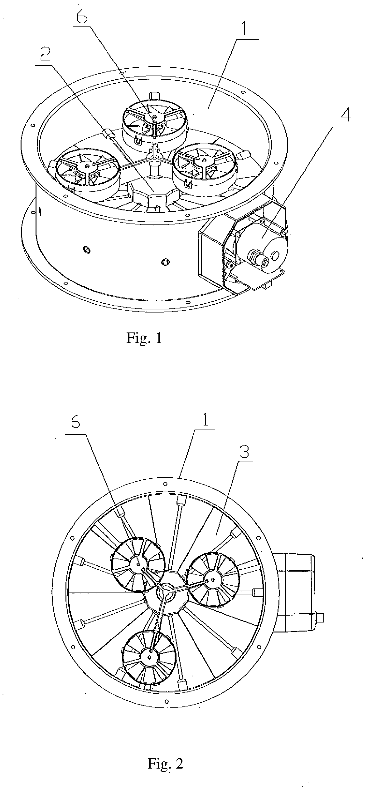
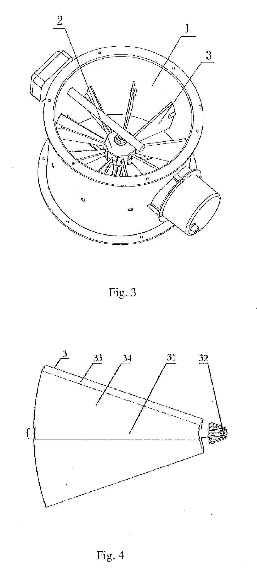
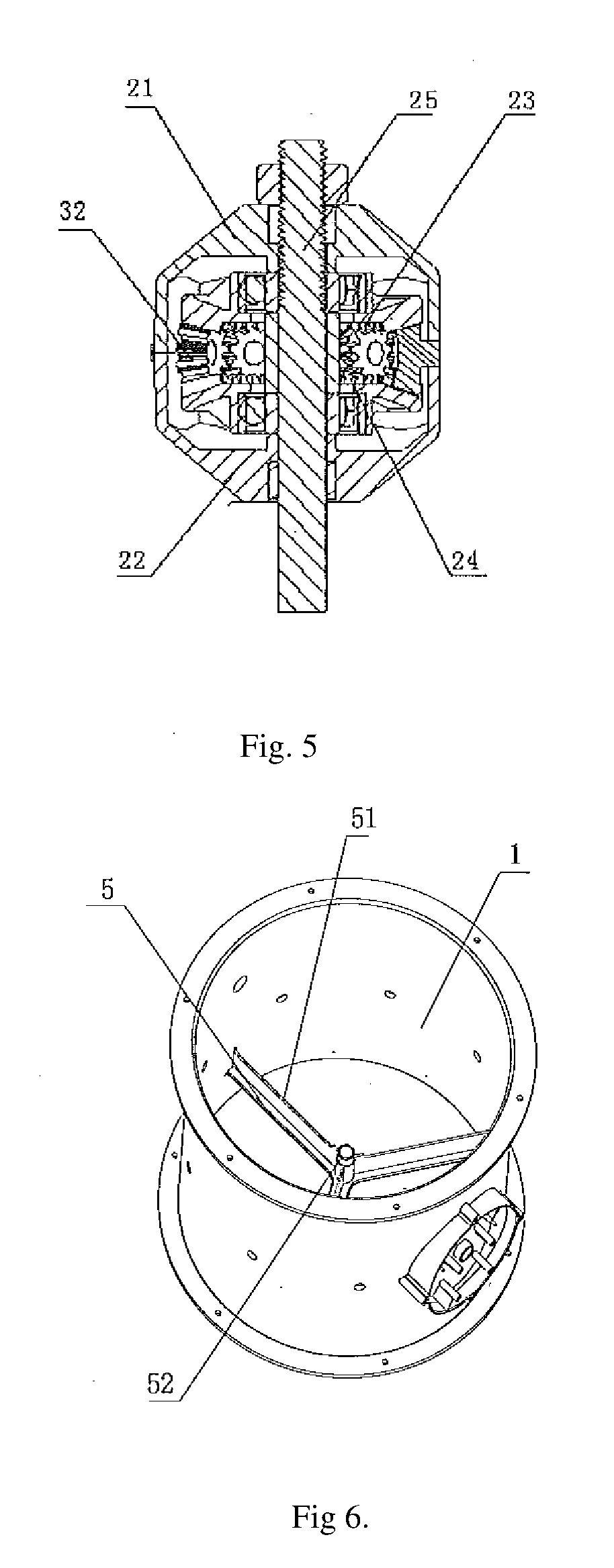
A ventilation valve, comprising a cylindrical valve body (1), a gear box (2), a plurality of fan-shaped vanes (3) and a drive device (4), the gear box (2) being arranged in the center of the valve body (1), and a geared mechanism being provided inside the gear box (2). The drive device (4), by means of a geared drive mechanism, cause the vanes (3) to rotate in a same direction, each around its own central shaft; the vanes (3) are arranged within the valve body (1) in a uniform distribution; the geared mechanism comprises a first central gear (23) and a second central gear (24) fitted on a same supporting shaft (25); between the first central gear (23) and the second central gear (24) are provided a plurality of gears, one each of which is arranged at the end of one of said central shafts which extends to within the gear box (2), each of said gears engaging with both said first central gear (23) and said second central gear (24). Also arranged within the valve body (1) is one or a plurality of airflow meters (6), the distance between the central axis of each of said one or plurality of airflow meters (6) and the central axis of the valve body (1) is different. The present ventilation valve precisely controls airflow and is safe and reliable, while featuring improved geared mechanism security and reduced wear and tear, thus prolongs the service life of the ventilation valve.

Description

CROSS-REFERENCE TO RELATED APPLICATIONS[0001]The present application is the US National Stage Entry under 35 U.S.C. 371 based on and claiming the benefit of PCT Application No. PCT / CN2016 / 080990, filed May 4, 2016, which claims the benefit of Chinese Patent Application Serial No. 201610200092.7, filed Mar. 31, 2016.INCORPORATION BY REFERENCE[0002]The disclosures of PCT Application No. PCT / CN2016 / 080990, filed May 4, 2016, and Chinese Patent Application Serial No. 201610200092.7, filed Mar. 31, 2016, are incorporated by reference herein for all purposes as if presented in their entirety.TECHNICAL FIELD[0003]The present invention relates to a ventilation valve.BACKGROUND ARTS[0004]The ventilation valve is a type of regulation valve with a simple structure and wide application. It can be used as a control device to control or shutoff gas flow rates, which can be applied to ventilation and environmental protection projects across various industries such as chemical industry, building ma...

Claims


Application Information

Patent Timeline
IPC IPC(8): F24F7/00
CPCF24F7/00F16K1/22F16K24/04F16K31/535F16K37/00F16K1/223F24F13/10F16K1/2014F16K1/2021F16K1/36F16K31/53F16K1/20F16K1/18
Inventor RUAN, HONGZHENGTANG, GUANGYE
Owner E3 GREEN TECH CO LTD
Learn More