Measurement system

a measurement system and measurement technology, applied in the field of measurement systems, can solve the problems of reducing the peak magnetic field strength, unsuitable packaging for harsh environments,

Active Publication Date: 2015-06-18
TDK MICRONAS GMBH
View PDF4 Cites 7 Cited by
  • Summary
  • Abstract
  • Description
  • Claims
  • Application Information

AI Technical Summary

Benefits of technology

[0014]A number of advantages are achieved through a practical implementation, such as is presented by way of example in the figure descriptions. Mechanical tolerances arising as a result of sensor component manufacture, sensor assembly, sensor mounting in the system, system component manufacture, system assembly, etc., can be compensated for at least partially by the adjustability between minimum and maximum. Wide scattering of a switching point of the sensor is significantly reduced by this means.
[0015]Especially magnetic field sensors that are not programmable can thus be used for a great many applications. Similarly, magnetic tolerances that arise in manufacture of the magnet due to suboptimal magnetization of the magnet, inhomogeneities of the magnet material, etc., can be compensated for. By the same token, technological tolerances in the manufacture of the magnetic field sensors, for example in the semiconductor process, can be compensated for. The adjustment is extremely simple here: by simply rotating the magnet, the switching point of the sensor in the overall system can be adjusted and the aforementioned tolerances can be compensated for at least partially.

Problems solved by technology

However, this type of packaging is unsuited for harsh environments, particularly that of an automobile.
This leads to a decrease in the peak magnetic field strength as a tooth passes through the magnetic field in proximity to the measuring element.

Method used


Image

  • Measurement system
  • Measurement system
  • Measurement system

Examples


Embodiment Construction

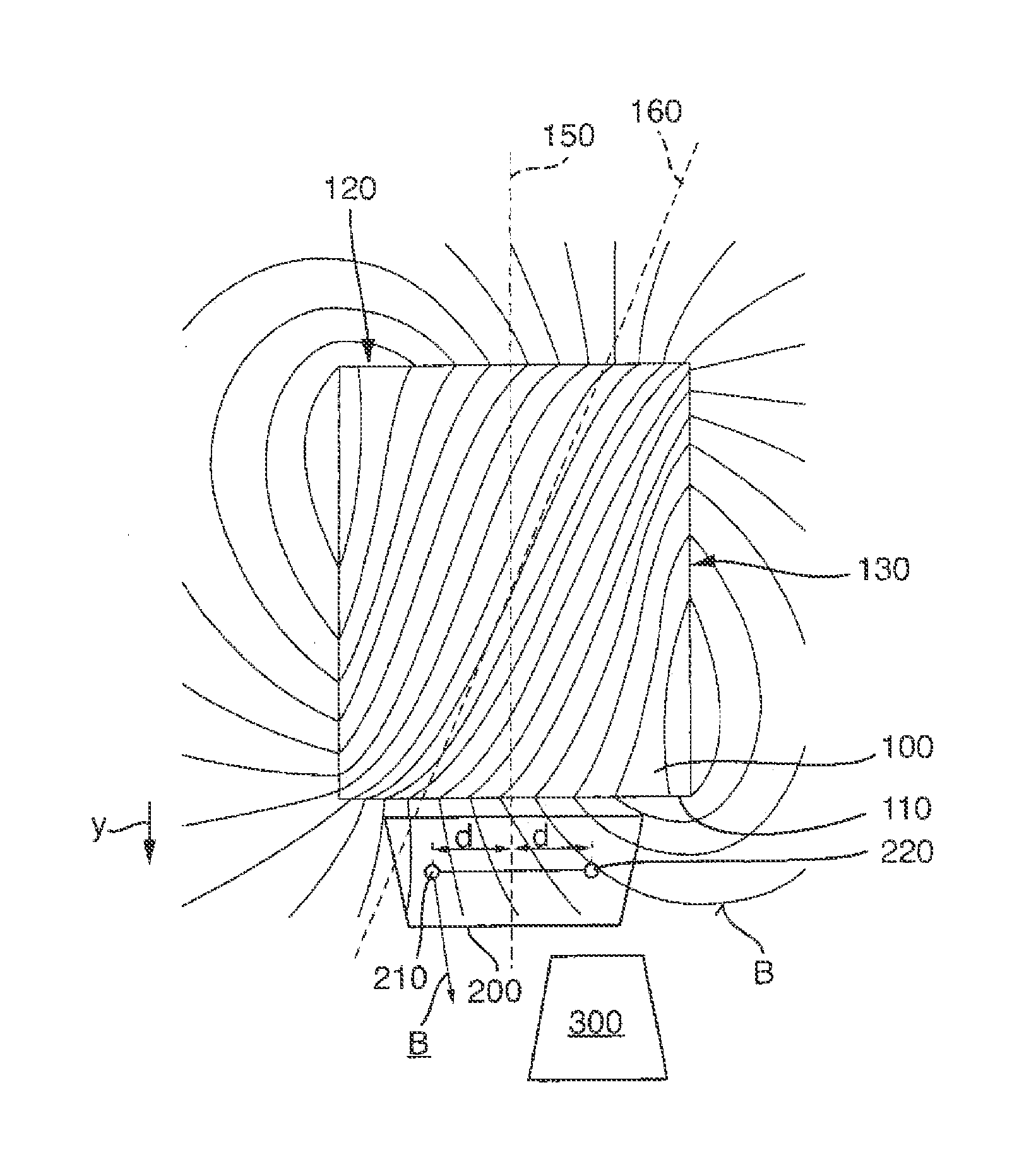
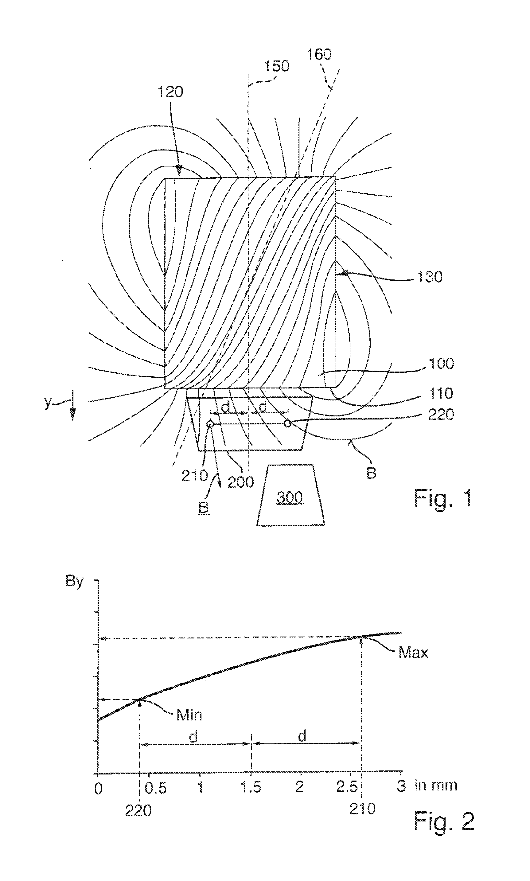
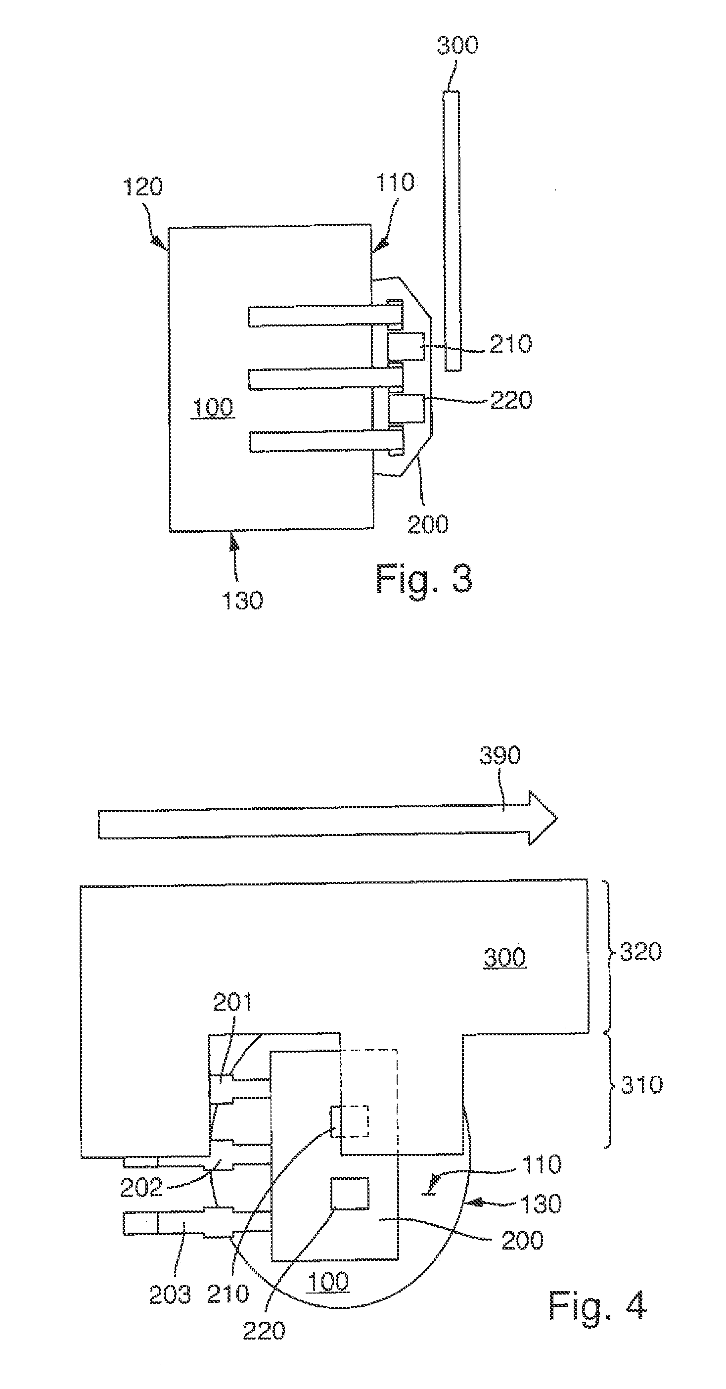
[0033]FIG. 1 shows a schematic sectional view in which a magnet 100, an IC package 200, and a detector 300 are shown in cross-section. Located in the IC package 200 are a first magnetic field sensor 210, for example a Hall effect sensor or a coil, and a second magnetic field sensor 220, for example likewise a Hall effect sensor or a coil.

[0034]In an embodiment from FIG. 1, an asymmetrically magnetized back bias magnet 100 is used for adjusting a switching point of the magnetic field sensor 210.

[0035]The measurement system has a sensor 210, 220 that is sensitive to magnetic fields, and has a magnet 100. The magnet 100 is located directly on one side of the magnetic field sensor 210. Located on the other side of the magnetic field sensor 210 is a detector 300, which can also be referred to as a target. Accordingly, the detector 300 is in front of the magnetic field sensor 210 and the magnet 100 is behind it, for example. The magnetic field sensor 210 is located in a package 200 togeth...


PUM


Abstract

A measurement system having a first magnetic field sensor and having a magnet for generating a magnetic field, in which the magnet has a first pole face and a second pole face, wherein an axis of rotation is defined perpendicular to the first pole face and perpendicular to the second pole face, wherein the magnet is supported for rotation about the axis of rotation, in which the first magnetic field sensor is positioned facing the first pole face and at a distance from the axis of rotation, in which the magnet has a rotational asymmetry of the flux density in the region of the first pole face, wherein the flux density of the magnet in the first magnetic field sensor can be adjusted between a maximum and a minimum by rotation of the magnet about the axis of rotation.

Description

[0001]This nonprovisional application claims priority under 35 U.S.C. § 119(a) to German Patent Application No. 10 2013 020 578.6, which was filed in Germany on Dec. 13, 2013, and which is herein incorporated by reference.BACKGROUND OF THE INVENTION[0002]1. Field of the Invention[0003]The present invention relates to a measurement system.[0004]2. Description of the Background Art[0005]Known from WO 2010 / 060607 A2, which corresponds to U.S. Pat. No. 8,680,847, which is incorporated herein by reference, is an IC package with a semiconductor chip with an integrated circuit and an integrated magnetic sensor. Spaced apart from the package of the semiconductor chip is a permanent magnet whose magnetic flux penetrates the sensor. If an object to be measured approaches the head end of the semiconductor chip, the magnetic flux density through the sensor changes.[0006]Integrated magnetic Hall effect sensors in which a permanent magnet is incorporated into the IC package are known from U.S. Pa...

Claims


Application Information

Patent Timeline
Patent Type & Authority Applications(United States)
IPC IPC(8): G01B7/30
CPCG01B7/30G01D5/24438G01D5/147
Inventor BONDAR, YAN
Owner TDK MICRONAS GMBH
Why Eureka
Try Eureka