Wire harness

a wire harness and wire technology, applied in the direction of insulated conductors, cables, conductors, etc., can solve the problem that the temperature of high-tension electric wires is unlikely to decreas

Active Publication Date: 2015-06-18
YAZAKI CORP
View PDF51 Cites 5 Cited by
  • Summary
  • Abstract
  • Description
  • Claims
  • Application Information

AI Technical Summary

Benefits of technology

[0024]According to the wire harness in the configuration (7) above, it is also possible to obtain the following effects in addition to the effects in the configuration (4) above. That is, it is possible to reflect heat from the outside using the heat reflecting portion that is formed as an add-on component or an add-on member which is added to the outer surface of the exterior member.
[0025]According to the wire harness in the configuration (8) above, it is also possible to obtain the following effects in addition to the effects in the configurations (5) to (7) above. That is, it is possible to reflect heat from the outside using the heat reflecting portion that is formed as a portion which has a white color or a bright color close to the white color, or is formed as a portion which is also glossy.

Problems solved by technology

In addition, when the collected heat cannot be efficiently transferred to the exterior member, and cannot be efficiently radiated from the exterior member to the outside, the temperature of the high-tension electric wire is unlikely to decrease.

Method used


Image

  • Wire harness
  • Wire harness
  • Wire harness

Examples


embodiment 1

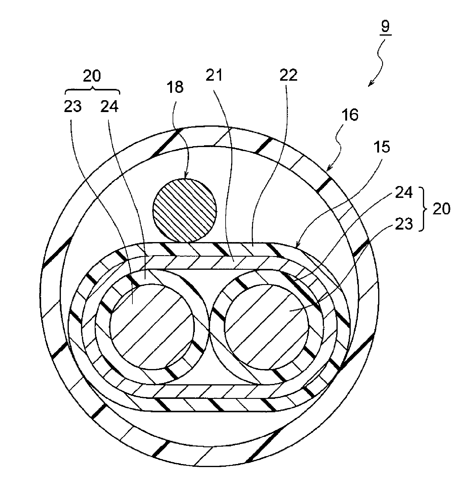
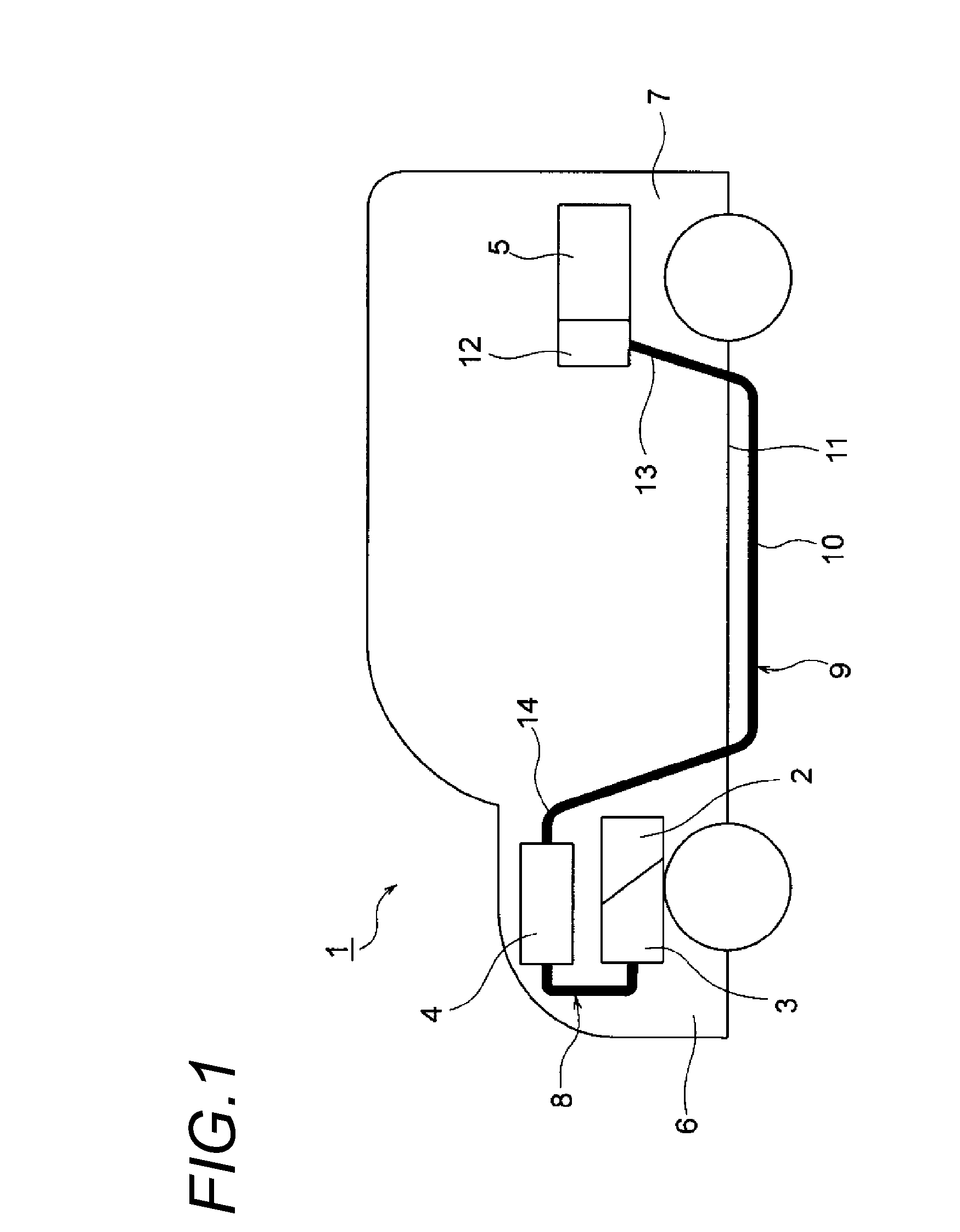
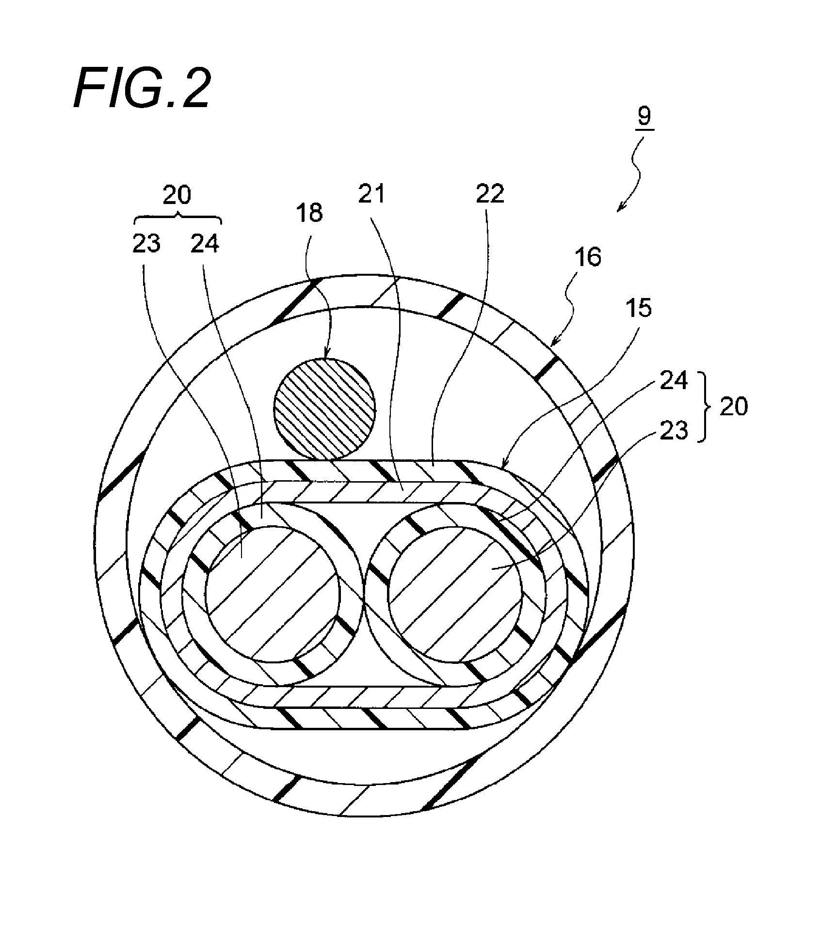
[0034]Hereinafter, a wire harness according to Embodiment 1 will be described with reference to FIGS. 1 to 4D. FIG. 1 is a schematic diagram illustrating the routing of the wire harness. FIG. 2 is a diagram illustrating the configuration of the wire harness, FIG. 3 is a diagram illustrating the configuration of an exterior member, and FIGS. 4A to 4D are diagrams illustrating examples of a heat reflecting portion and an identification portion.

[0035]In the following example, the wire harness according to Embodiment 1 is routed in a hybrid vehicle (may be an electric vehicle or a general vehicle).

[0036]In FIG. 1, reference sign 1 indicates a hybrid vehicle. The hybrid vehicle 1 is a vehicle that is driven by the combination of two power sources such as an engine 2 and a motor unit 3. A battery 5 (in other words, battery pack) supplies electrical power to the motor unit 3 via an inverter unit 4. In this example, the engine 2, the motor unit 3, and the inverter unit 4 are mounted in an e...

embodiment 2

[0084]The configuration of a wire harness according to Embodiment 2 will be described with reference to FIG. 5. FIG. 5 is a diagram illustrating the configuration of the wire harness according to Embodiment 2. The same reference numerals and signs will be assigned to the basically same configuration members as in Embodiment 1, and detailed description will be omitted.

[0085]In FIG. 5, the wire harness 9 includes the high-tension conductive path 15; the exterior member 16 that accommodates and protects the high-tension conductive path 15; and the shield connector 17 (refer to FIG. 3) that is provided at the terminal of the high-tension conductive path 15. The exterior member 16 may be formed to have not only a circular cross section as in Embodiment 1, but also an elliptical cross section (may be an oblong circular cross section) so that the shape of the exterior member 16 conforms to an exterior shape of the high-tension conductive path 15. The plurality of heat reflecting portions 2...

embodiment 3

[0087]Hereinafter, a wire harness according to Embodiment 3 will be described with reference to FIG. 6. FIG. 6 is a diagram illustrating the configuration of the wire harness according to Embodiment 3. The same reference numerals and signs will be assigned to basically the same configuration members as in Embodiments 1 and 2, and detailed description will be omitted.

[0088]In FIG. 6, the wire harness 9 includes the high-tension coaxial composite conductive path 32 which is a high-tension conductive path; the exterior member 16 that accommodates and protects the high-tension coaxial composite conductive path 32; and a shield connector (not illustrated) that is provided at the terminal of the high-tension coaxial composite conductive path 32. The plurality of heat reflecting portions 27 are provided in the exterior member 16. The plurality of identification portions 38 (refer to FIG. 3) are provided in the exterior member 16.

[0089]The high-tension coaxial composite conductive path 32 h...


PUM

PropertyMeasurementUnit
coloraaaaaaaaaa
tubular shapeaaaaaaaaaa
conductiveaaaaaaaaaa

Abstract

Disclosed is a wire harness including at least one conductive path, and an exterior member that accommodates and protects the conductive path. The exterior member is a molded resin component made of a resin material which has a black color or a dark color close to the black color.

Description

CROSS REFERENCE TO RELATED APPLICATIONS[0001]This application is a continuation of international patent application No. PCT / JP2013 / 074264, which was filed on Sep. 9, 2013 based on Japanese Patent Application No. 2012-198584 filed on Sep. 10, 2012, the contents of which are incorporated herein by reference.BACKGROUND OF THE INVENTION[0002]1. Field of the Invention[0003]The present invention relates to a wire harness that includes at least one conductive path, and an exterior member which accommodates and protects the conductive path.[0004]2. Description of the Related Art[0005]Typically, high-tension (that is, high-voltage) wire harnesses electrically connect a battery to an inverter unit, and the inverter unit to a motor unit in a hybrid vehicle or an electric vehicle. A wire harness disclosed in JP-A-2004-224156 includes a high-tension electric wire which is a high-tension conductive path, and an exterior member that accommodates the high-tension electric wire.SUMMARY OF THE INVENT...

Claims


Application Information

Patent Timeline
Patent Type & Authority Applications(United States)
IPC IPC(8): H01B7/29B60R16/02H01B7/00
CPCH01B7/292B60R16/0215H01B7/0045H01B3/004
Inventor INAO, SHINICHIADACHI, HIDEOMIOGUE, TAKESHIOGA, TATSUYASUGURO, MASAAKIOZAKI, YOSHIAKIYOSHIDA, HIROYUKI
Owner YAZAKI CORP
Why Eureka
Try Eureka