Thin film magnetic head, magnetic head and magnetic disk driving device

a magnetic head and magnetic disk technology, applied in the direction of maintaining the head carrier alignment, recording information storage, instruments, etc., can solve the problems of deterioration of the reliability of the magnetic disk driving device, coil film developing heat, and ineffective heat radiation of the coil film

Inactive Publication Date: 2005-11-08
TDK CORPARATION
View PDF14 Cites 7 Cited by
  • Summary
  • Abstract
  • Description
  • Claims
  • Application Information

AI Technical Summary

Benefits of technology

[0015]It is an object of the present invention to provide a thin film magnetic head in which the thermal expansion in the ABS due to the developed heat at a recording operation can be repressed, and thus, the head crash and the damage for a magnetic disk and magnetically recorded data can be inhibited.

Problems solved by technology

In this case, however, the coil film develop a heat.
As mentioned above, since the coil film is embedded in the insulating film made of an organic insulating material, and the insulating film is covered with the protection film made of alumina, etc., the coil film can not radiate the heat effectively.
Therefore, the above expansion in the ABS can easily crash the thin film magnetic head itself and the magnetic disk or damage the magnetic recorded data, resulting in the deterioration of the reliability of the magnetic disk driving device.
However, the disclosed technique dose not repress the thermal expansion of the protection film, but allows the thermal expansion as far as the protection film does not expands beyond the flat ABS by retreating the protection film from the ABS in advance.
Therefore, the disclosed technique can not solve the above problem.
Moreover, in the above technique, the complicate process is required that the protection film is flattened on the basis of the assumed expansion degree due to the developed heat at a recording operation.
In addition, the configuration of the slider, particularly the geometrical shape of the ABS is specified to a give shape, and thus, the ABS can not have another geometrical shape for improving the floating performance.

Method used


Image

  • Thin film magnetic head, magnetic head and magnetic disk driving device
  • Thin film magnetic head, magnetic head and magnetic disk driving device
  • Thin film magnetic head, magnetic head and magnetic disk driving device

Examples


Embodiment Construction

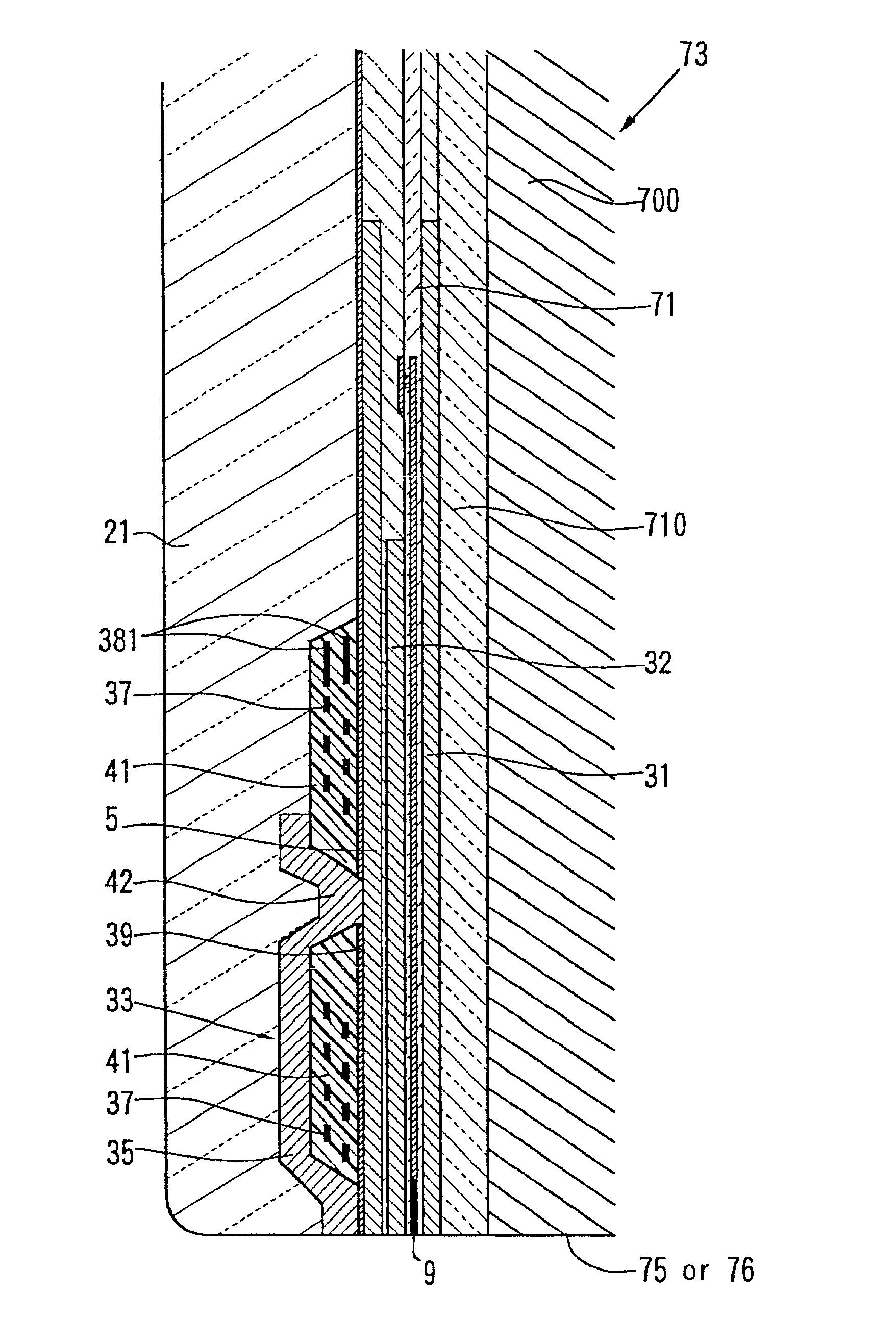
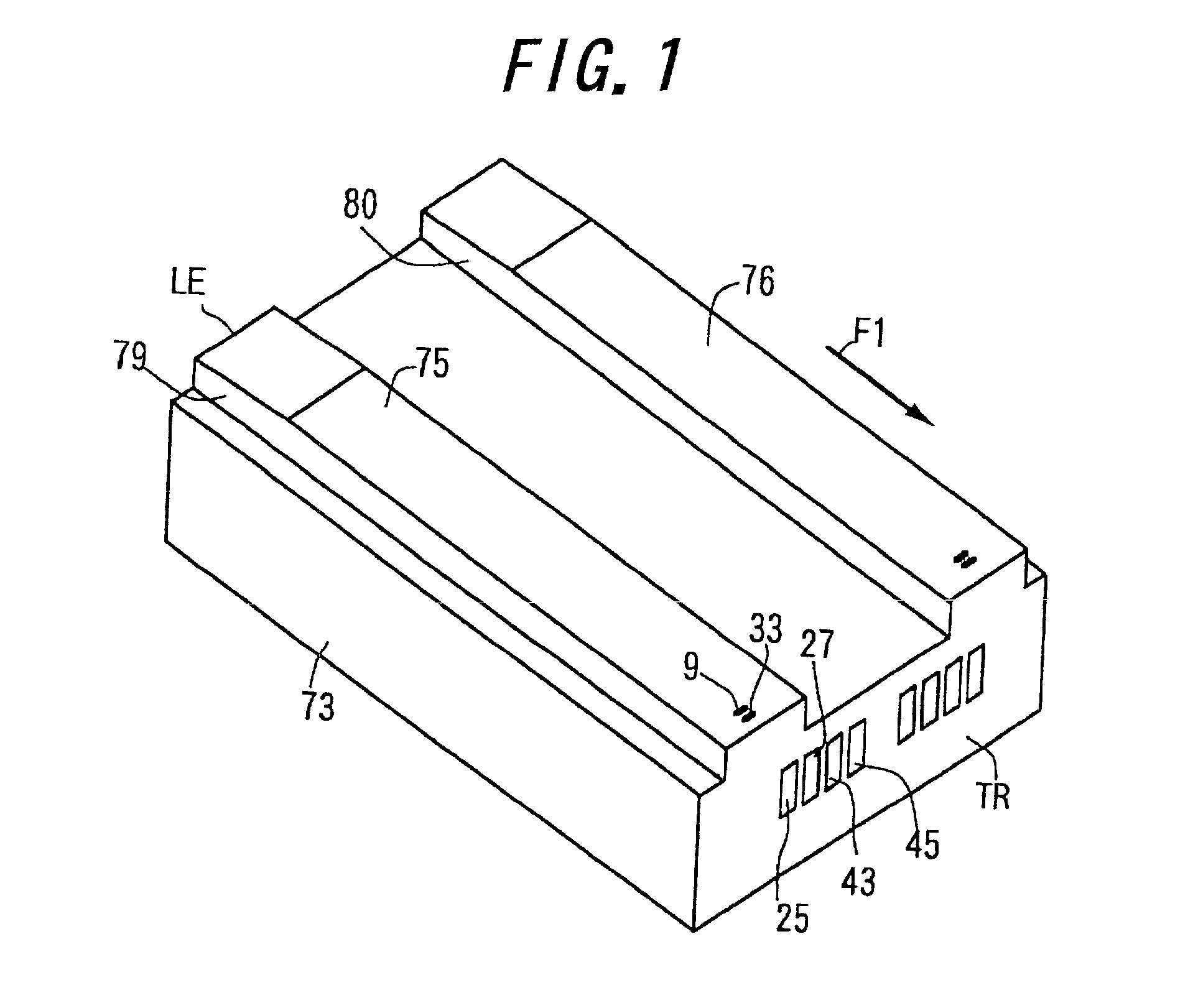
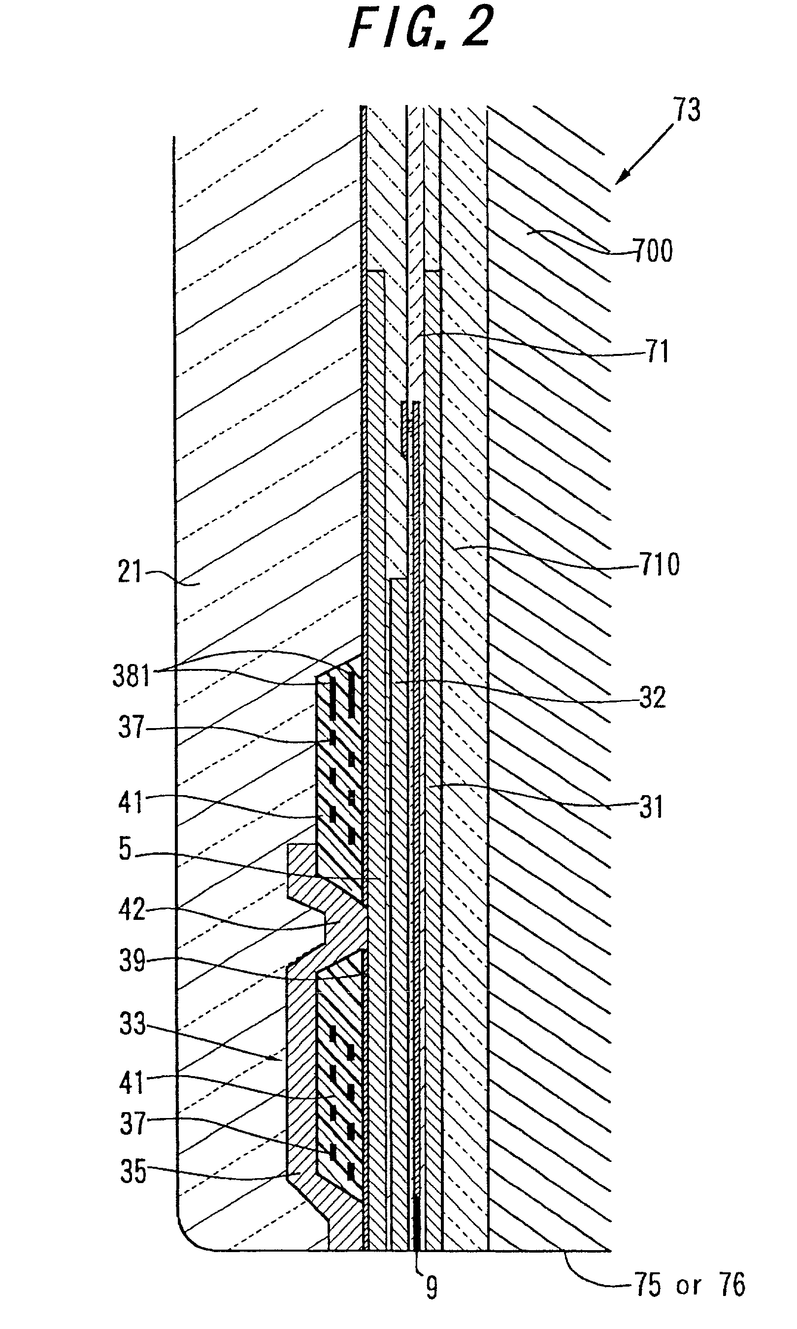
[0052]FIG. 1 is a perspective view showing a thin film magnetic head according to the present invention, and FIG. 2 is an enlarged cross sectional view of a portion of the thin film magnetic head shown in FIG. 1. In these figures, some constituent elements are depicted exaggeratedly.

[0053]The illustrated thin film magnetic head includes a slider 73, two inductive type electromagnetic conversion elements 33 and two magnetoresistive effective elements 9 (hereinafter, called as “MR element”s). The slider 73 has rail parts 79 and 80 on its medium opposing surface, and the surfaces of the rail parts 79 and 80 are employed as ABSs 75 and 76. The slider 73 is not always required to have the two rail parts 79 and 80. For example, it may have one to three rail parts or a flat surface without the rail. For improving its floating performance, the slider 73 may have rail parts with geometrical shapes. This invention can be applied for any kind of slider. The slider 73 may have a protection film...


PUM

PropertyMeasurementUnit
thicknessaaaaaaaaaa
thicknessaaaaaaaaaa
magneticaaaaaaaaaa

Abstract

A thin film magnetic head includes a slider, at least one inductive type electromagnetic conversion element and a thermal diffusion film. The inductive type electromagnetic conversion element includes a first magnetic film, a second magnetic film, a gap film, a coil film and an insulating film which are supported by the slider. The coil film is embedded in the insulating film. The thermal diffusion film is made of a metallic film, and disposed in the heat transmission path from the coil film toward the slider.

Description

BACKGROUND OF THE INVENTION[0001]1. Field of the Invention[0002]This invention relates to a thin film magnetic head, a magnetic head device and a magnetic disk driving device.[0003]2. Related Art Statement[0004]A floating type thin film magnetic head includes usually a writing element constructed of an inductive type electromagnetic conversion element and a reading element constructed of a magnetoresistive effective element. The inductive type electromagnetic conversion element is covered with a protection film which is made of an inorganic insulating material such as alumina and constitutes an outermost surface layer of the magnetic head in the air outflow side.[0005]The inductive type electromagnetic conversion element includes a first and a second magnetic films, a gap film, a coil film and an insulating film, etc. The edge portions of the first and second magnetic films, which are opposed each other via the gap film in the air bearing surface (hereinafter, called as “ABS”) of th...

Claims


Application Information

Patent Timeline
Patent Type & Authority Patents(United States)
IPC IPC(8): G11B5/31G11B5/39G11B19/04G11B5/40G11B5/60
CPCG11B5/3106G11B5/3133G11B5/3967G11B5/40G11B19/04
Inventor YOSHIDA, MAKOTOOIKE, TAROYAMANAKA, NOBORU
Owner TDK CORPARATION
Why Eureka
Try Eureka