Heat-absorbing device with phase-change material

a phase change, heat-absorbing technology, applied in indirect heat-absorbing devices, semiconductor/solid-state device details, lighting and heating apparatus, etc., can solve the problems of inability to react, damage or loss of component efficiency, instantaneous and momentary positive temperature differences,

Active Publication Date: 2013-11-28
COMMISSARIAT A LENERGIE ATOMIQUE ET AUX ENERGIES ALTERNATIVES
View PDF0 Cites 5 Cited by
  • Summary
  • Abstract
  • Description
  • Claims
  • Application Information

AI Technical Summary

Problems solved by technology

In certain cases of uncontrolled operation, the consequence of these thermal fluxes may lead to an instantaneous and momentary positive temperature difference compared to their nominal operating temperature.
In certain cases, this temperature difference may lead to damaging or loss of efficiency of the component.
Radiator type devices exist which make it possible to evacuate continuously the heat emitted by the components, however they are not always capable of reacting when a random thermal flux is emitted.
These circuits are bulky and require means to circulate the fluid.
Moreover, as previously, they are not always capable of absorbing a quantity of heat emitted randomly.
Moreover, these systems are not capable of responding at a speed (or frequency) greater than the speed of appearance of the temperature difference.
However, the quantity of heat absorbed is limited by the quantity of phase-change material found in contact with the panel.
In addition, since phase-change materials have poor thermal conductivity, forming systems having a large thickness of phase-change material cannot be envisaged.
Moreover, a large thickness of material does not offer a response speed adapted to temperature difference appearance speeds.
Yet, in the case of a large thickness of material, this extraction is not easy.

Method used


Image

  • Heat-absorbing device with phase-change material
  • Heat-absorbing device with phase-change material
  • Heat-absorbing device with phase-change material

Examples


Embodiment Construction

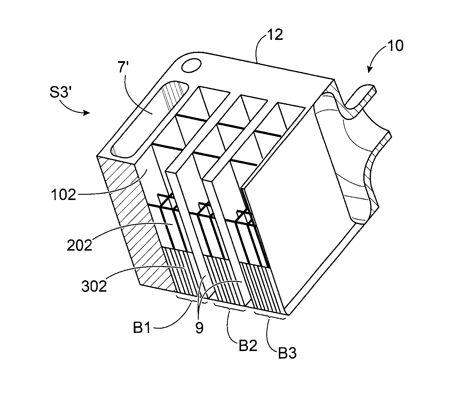
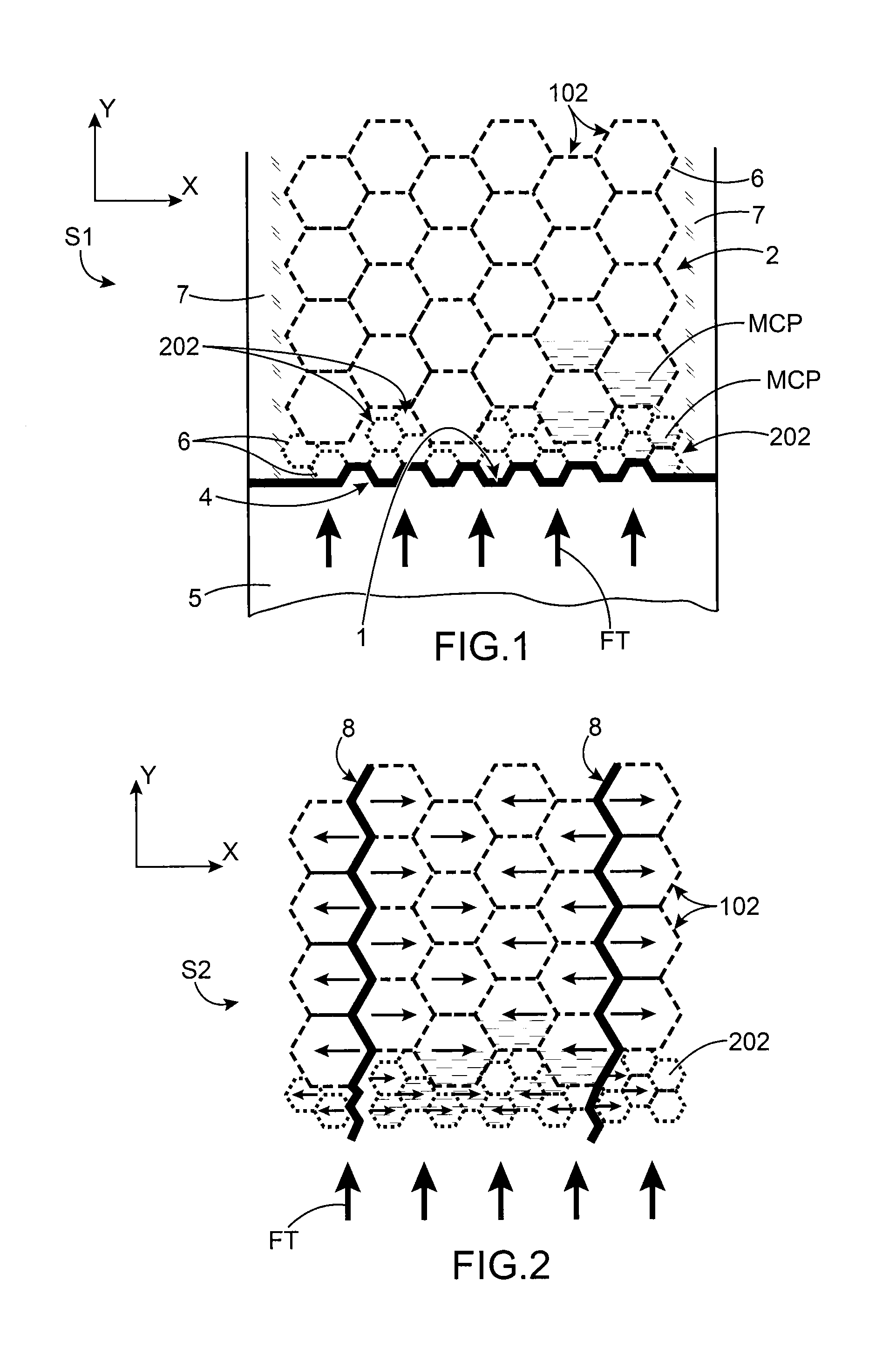
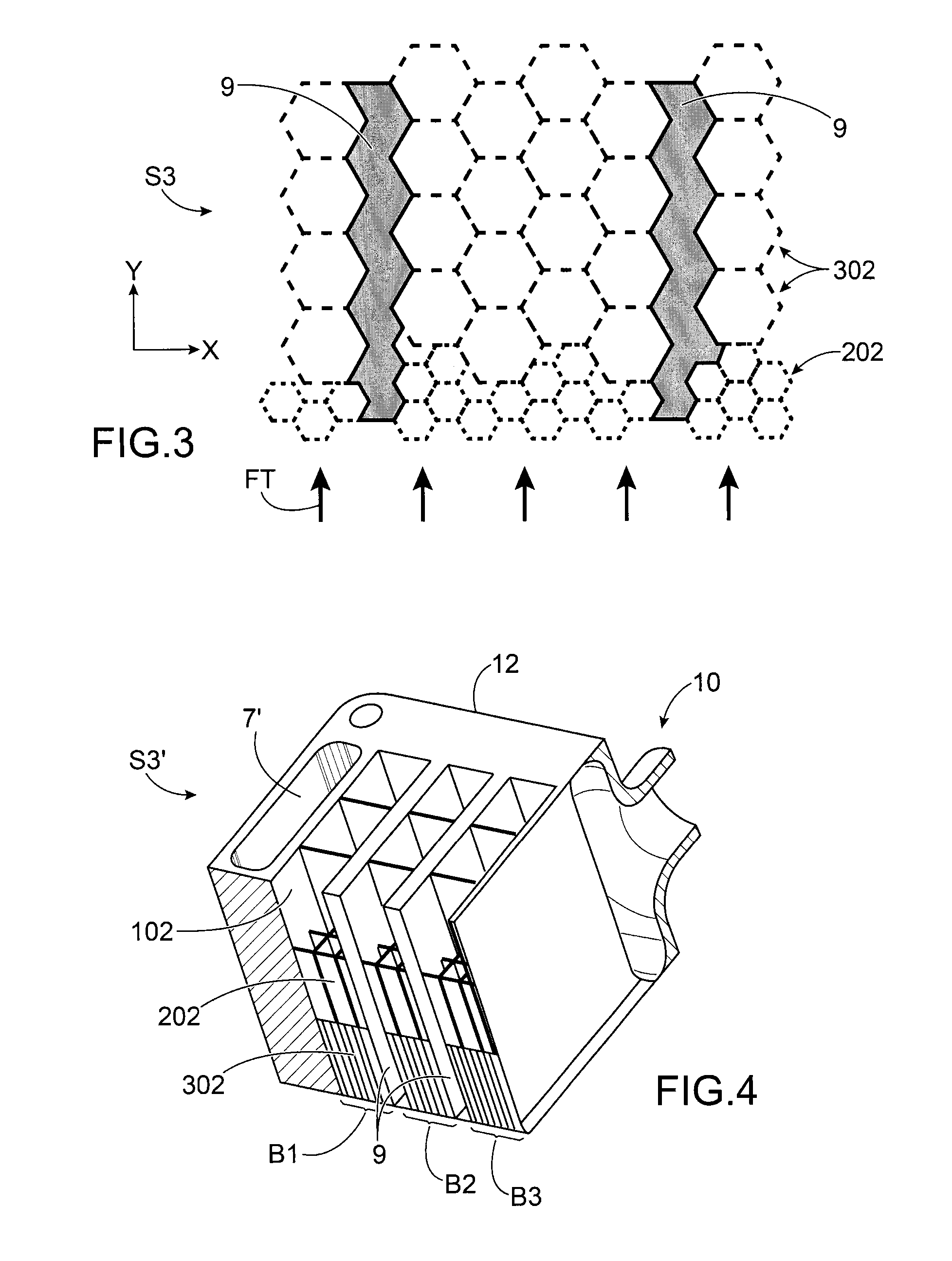
[0011]It is consequently an aim of the present invention to offer an optimised heat absorbing device being capable of absorbing thermal fluxes emitted by a heat source imposing multiple transitory conditions of operation, the transitory conditions being able to be simultaneous or staggered over time.

[0012]The aforementioned aim is attained by a device comprising a plurality of stacked cells containing a phase-change material, the structure comprising several sizes of cell, these sizes of cell being determined to absorb as best as possible the peaks according to their frequency of appearance, the number of cells being determined as a function of the relative amplitude of the peaks.

[0013]According to the invention, a plurality of cells is implemented, the size of which is a parameter for adjusting the kinetics of the change of phase. In fact the phase-change material contained in a larger cell melts completely over a longer time than that contained in a smaller cell. Consequently, for...


PUM

PropertyMeasurementUnit
temperatureaaaaaaaaaa
phase-change temperaturesaaaaaaaaaa

Abstract

A heat absorbing device including a structure including plural individual cells delimited by an envelope made of a material that has good thermal conductivity and includes at least one phase-change material, the cells being stacked on top of one another from an end surface so that the structure extends in a direction of thermal flux, the flux being made up of two notable periodic thermal events, the structure including two different sizes of cells. The sizes of the cells are determined as a function of frequency of the thermal events of the thermal flux and a distribution of a number of cells of each size is determined as a function of amplitudes of each event.

Description

TECHNICAL FIELD AND PRIOR ART[0001]The present invention relates to a heat absorbing device with phase-change material, particularly adapted to the absorption of the heat emitted by systems in the field of electronics, microelectronics and power electronics.[0002]Electronic components are sources of multiple emissions of thermal fluxes, these being able to be alternatively transitory and / or stationary depending on their state of operation. In certain cases of uncontrolled operation, the consequence of these thermal fluxes may lead to an instantaneous and momentary positive temperature difference compared to their nominal operating temperature. In certain cases, this temperature difference may lead to damaging or loss of efficiency of the component.[0003]Consequently, in order to ensure the correct operation of electronic components, a planned evacuation of the heat is required.[0004]The thermal fluxes have variable peaks of amplitudes and periods and different appearance frequencies...

Claims


Application Information

Patent Timeline
Patent Type & Authority Applications(United States)
IPC IPC(8): F28F7/00B23P15/26
CPCF28F7/00B23P15/26F28D20/023H01L23/427H01L2924/0002Y10T29/4935Y02E60/14H01L2924/00F28D20/02F28D20/021
Inventor GAVILLET, JEROME
Owner COMMISSARIAT A LENERGIE ATOMIQUE ET AUX ENERGIES ALTERNATIVES
Why Eureka
Try Eureka