Thermal spreading sheet and method for manufacturing the same, and backlight unit with the same

a technology of thermal spreading sheet and backlight unit, which is applied in the direction of lighting and heating apparatus, instruments, optical elements, etc., can solve the problems of reflective sheet deformation, and achieve the effect of effectively absorbing and spreading heat of reflective sheet and preventing damage of thermal spreading sh

Inactive Publication Date: 2007-04-26
LG ELECTRONICS INC
View PDF15 Cites 7 Cited by
  • Summary
  • Abstract
  • Description
  • Claims
  • Application Information

AI Technical Summary

Benefits of technology

[0027] The thermal spreading sheet according to the present invention can absorb and spread heat of the reflective sheet effectively. Also, it i

Problems solved by technology

The reflective sheet is overheated by the transferred heat,

Method used


Image

  • Thermal spreading sheet and method for manufacturing the same, and backlight unit with the same
  • Thermal spreading sheet and method for manufacturing the same, and backlight unit with the same
  • Thermal spreading sheet and method for manufacturing the same, and backlight unit with the same

Examples


first embodiment

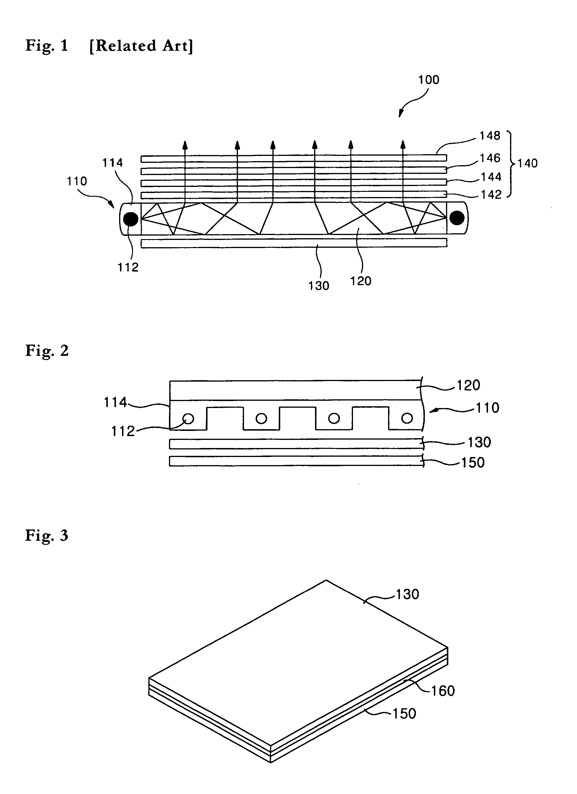
[0044] The major components contained in the thermal spreading sheet according to the present invention are graphite powder and binder. Graphite powder is mixed with viscous binder, and their mixture is applied to the bottom surface of the reflective sheet 130. Preferably, the binder may contain the material which has high thermal conductivity and high heat resistance, such as polyurethane, acrylic or silicon.

[0045] The binder used in the first embodiment of the present invention is polyurethane. The physical and chemical properties of polyurethane are as follows.

[0046] Polyurethane is rubber-state elastic body of polymer compounds having urethane bond—OCONH— within the molecule. Recently, the use of polyurethane has been extended to various fields such as urethane rubbers, synthetic fibers, adhesives, paints, urethane forms, automobile bumpers, etc.

[0047] Generally, polyurethane is prepared by addition polymerization of diol (e.g. 1,4-buthandiol, etc.) and di-isocyanate (diphenyl...

second embodiment

[0051] Prior to explaining the thermal spreading sheet and the method for manufacturing the same according to the present invention, nano composite will be explained.

[0052] Nano composite is a mixture of at least two components. Nano composite means an artificially produced material from chemically distinguishable components that are combined with maintaining each component's properties so that each component's unique mechanical, physical, and chemical properties are reacted in mutually complementary way to achieve better property than each separate component.

[0053] Generally, component of the composite material for structure material is classified to base and reinforcement material.

[0054] Base bonds reinforcement materials each other, protects reinforcement materials from external environment, maintains the shape of composite material, and has enduring structure within composite material.

[0055] Reinforcement material enables composite material to have more excellent mechanical p...


PUM


Abstract

The present invention relates to a thermal spreading sheet with superior ductility and strength, and a method for manufacturing the same. One method for manufacturing the thermal spreading sheet according to the present invention comprises the steps of mixing graphite powder and binder; and applying the mixture of graphite powder and binder onto the surface of a reflective sheet to form the thermal spreading sheet with a predetermined thickness. The binder is preferable to contain polyurethane, acrylic or silicon. And, the mixture of graphite powder and binder is preferable to contain copper or silver. Another method for manufacturing the thermal spreading sheet according to the present invention comprises the steps of adding an acrylic resin into a fine graphite particle to form a nano-composite; and compressing the nano-composite at a high temperature. The method for manufacturing the thermal spreading sheet further comprises the step of adding a resin having high thermal conductivity into the nano-composite.

Description

BACKGROUND OF THE INVENTION [0001] 1. Field of the Invention [0002] The present invention relates to a thermal spreading sheet and a method for manufacturing the same. Particularly, the present invention relates to a thermal spreading sheet with superior ductility and strength, and a method for manufacturing the same. [0003] 2. Description of the Related Art [0004] Liquid Crystal Display device (hereinafter, “LCD device”) is an electrical device which changes electrical data generated from many apparatuses into visual data, and transfers them by using variation of crystal transmissivity according to applied voltage. [0005] LCD device is a device for displaying information, but does not have a light source in itself. Thus, LCD device needs an extra device to uniformly brighten the entire screen of LCD device by a light source installed on the rear surface of LCD device. As such extra device, Back Light Unit (hereinafter, “BLU”) providing a light to the screen of LCD device is used. [...

Claims


Application Information

Patent Timeline
IPC IPC(8): F21V29/00F21V29/505
CPCG02B6/0055G02B6/0068G02B6/0085G02F1/1335
Inventor HWANG, KAB JIN
Owner LG ELECTRONICS INC
Why Eureka
Try Eureka