Motor drive device for electric power steering including heat sink and external connector

a technology of electric power steering and drive device, which is applied in the direction of electrical steering, association with control/drive circuit, transportation and packaging, etc., can solve the problem that the portion of the flat plate does not necessarily serve as a heat sink, and achieve the effect of small and compact structure and high cooling performan

Inactive Publication Date: 2018-03-06
NIDEC ELESYS
View PDF15 Cites 6 Cited by
  • Summary
  • Abstract
  • Description
  • Claims
  • Application Information

AI Technical Summary

Benefits of technology

[0012]In this motor drive device, a motor case that stores a motor and a controller case that stores a controller of controlling the motor are unitarily coupled to each other in the direction of the rotating shaft of the motor. In addition, a connection port for an external connector included in the controller is also provided in the direction of the rotating shaft of the motor. Such a structure achieves a small and compact structure that can be connected in the direction of the rotating shaft. In particular, it is advantageous to achieve a motor drive device that is narrow in the radial direction.
[0013]In addition, the control unit case transfers heat generated by power consumption and the like, and serves also as a heat sink for cooling with outside air, thus achieving an efficient cooling structure. The control unit case includes the flat plate extending in the direction perpendicular to the rotating shaft, and the external wall having the cylindrical shape in the circumferential direction. The outer circumference of the external wall is in contact with the outside air. The portion or the entirety of the flat plate and the external wall of this controller case have the structure made by metal die casting. The flat plate thus has the structure in contact with the power module, the structure encompassing an indirect structure, described later. Accordingly, this structure efficiently absorbs heat generated by the power module and the like. The heat is transferred to the external wall formed in a coupled and unitary manner with the flat plate, and released to the outside air from the outer circumferential surface of the external wall. Preferably, the entire external wall serves as a heat sink. Alternatively, a part of the external wall may serve as a heat sink. Preferably, portions having a structure in contact with the power module as a heat generating portion serve as a heat sink. Accordingly, the other portions of the flat plate do not necessarily serve as a heat sink. In comparison with the case of including a heat sink separately from the controller case, the present structure can achieve a more compact and smaller motor drive device.
[0015]As with the first embodiment, in this second embodiment, the motor case and the controller case are coupled unitarily to each other in the direction of the rotating shaft of the motor. This achieves a small and compact structure. In particular, it is advantageous to achieve the motor drive device that is narrow in the radial direction.
[0016]In addition, the power module of this embodiment is configured by a power module that is formed by molding an integrated circuit including an inverter circuit with material including resin, ceramic or the like. The power module has a small and compact structure as one power LSI component. The power module may have a structure where multiple bare chips configuring a part of the inverter circuit are disposed on an LSI base. As a result, a complex inverter circuit can be configured, and the designing flexibility can be improved. In addition, in comparison with a substrate structure formed by conventional discrete inverter configuration components, the size is significantly reduced. Accordingly, in comparison with the conventional art, the motor drive device having a significantly reduced size can be achieved.
[0018]As with the first embodiment, in this third embodiment, the motor case and the controller case are unitarily coupled to each other in the direction of the rotating shaft of the motor. Thus, the small and compact structure can be achieved. In particular, it is advantageous to achieve the motor drive device that is narrow in the radial direction.
[0019]In addition, this embodiment further includes a metal radiator plate and a heat conductive member. Thus, the motor drive device having a high cooling performance can be achieved.

Problems solved by technology

Accordingly, the other portions of the flat plate do not necessarily serve as a heat sink.

Method used


Image

  • Motor drive device for electric power steering including heat sink and external connector
  • Motor drive device for electric power steering including heat sink and external connector
  • Motor drive device for electric power steering including heat sink and external connector

Examples


Embodiment Construction

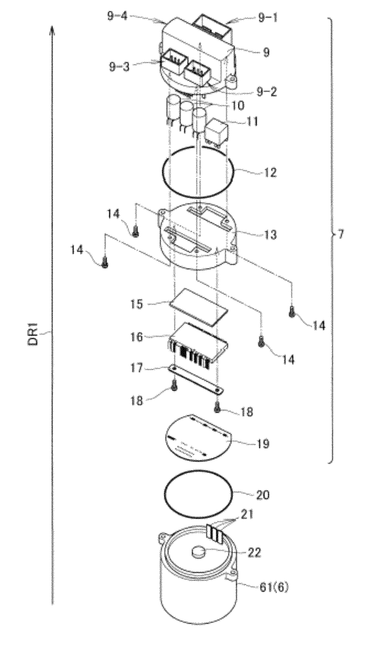
[0036]Preferable embodiments of the present invention are hereinafter described with reference to the drawings. In the following description, the direction along the rotating shaft (rotation axis) of a motor is referred to as a direction of the rotating shaft, and a direction perpendicular to the rotating shaft is referred to as a radial direction.

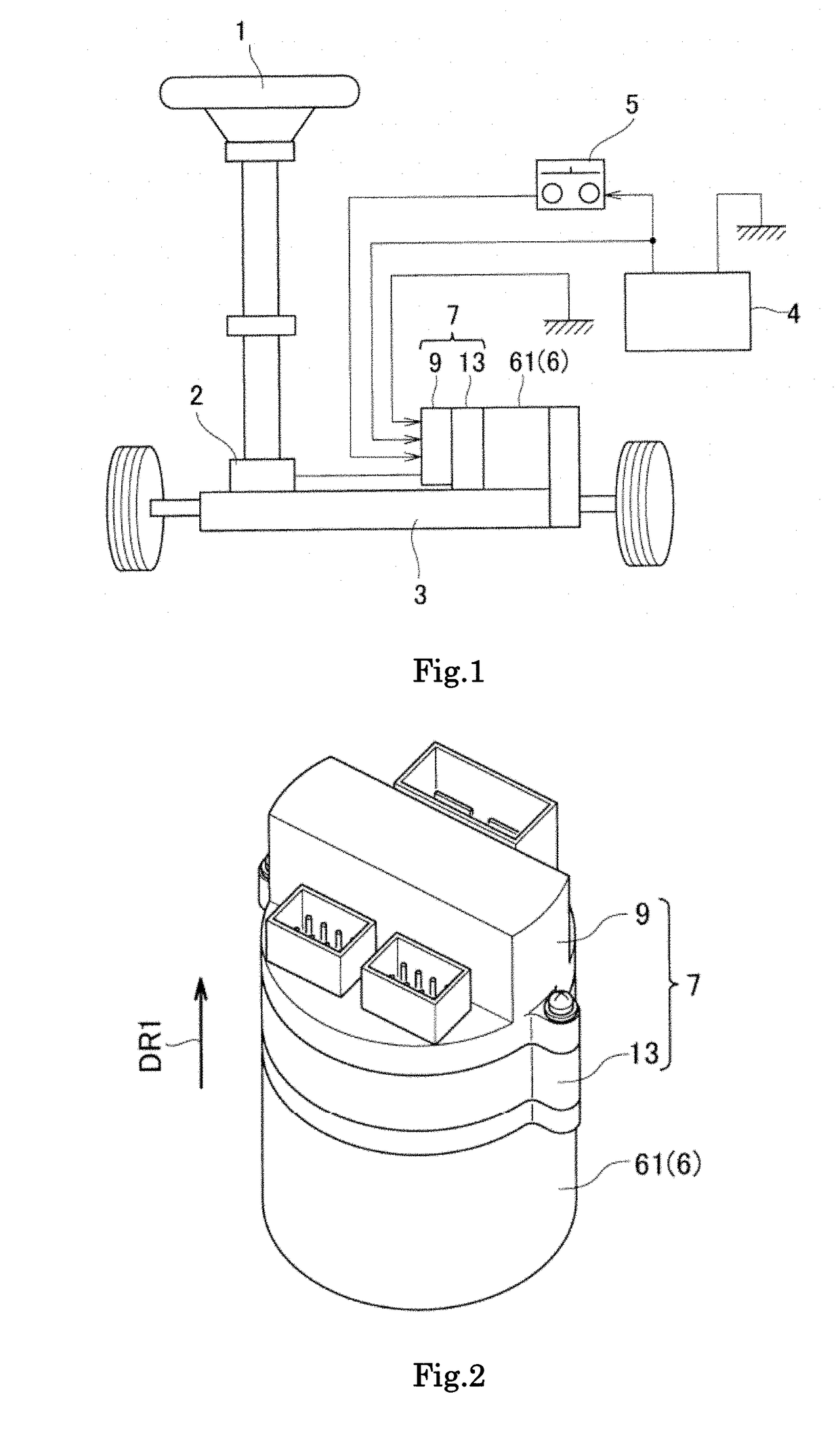
[0037]FIG. 1 shows an example of a schematic configuration of an electric power steering device. In the example in FIG. 1, the electric power steering device includes an electronic control unit 7. More specifically, the electric power steering device includes an assist torque mechanism that applies an assist torque (also referred to as an additional torque) to a steering system from a steering handle (e.g., steering wheel) 1 of a vehicle to steered wheels (e.g., front wheels) of the vehicle.

[0038]In the example in FIG. 1, the steering system couples a rotating shaft (also referred to as a pinion shaft or an input shaft) to the steering han...


PUM


Abstract

In this motor drive device, a motor case which stores a motor and a controller case which stores a controller of controlling the motor are unitarily coupled to each other in a direction of the rotating shaft of the motor. In addition, a connection portion for an external connector included in the controller is also provided in the direction of the rotating shaft of the motor. Such a structure achieves a small and compact structure which can be connected in the direction of the rotating shaft.

Description

FIELD OF THE INVENTION[0001]The present invention relates to a motor drive device for an electric power steering device. This motor drive device includes a motor and an electronic control unit (abbreviated as ECU) for controlling the motor.[0002]In this field a device which controls an actuator such as a motor or the like has been called generally as ECU. The ECU or the electrical control unit includes a power module or power converter, a heat sink, a controller and a connector.DESCRIPTION OF THE RELATED ART[0003]A vehicle, such as an automobile, may include an electric power steering device. An electric power steering device generates an assist torque that assists a steering torque in a steering system generated by a driver's operation to a steering handle. The generation of assist torque allows an electric power steering device to reduce the load on the driver. An assist torque mechanism that applies an assist torque causes a torque sensor to detect the steering torque in the stee...

Claims


Application Information

Patent Timeline
Patent Type & Authority Patents(United States)
IPC IPC(8): H02K11/00H02K5/22B62D5/04H02K11/33H02K9/22
CPCH02K11/33H02K5/225B62D5/0406H02K9/22B62D5/04B62D5/0457H02K9/227
Inventor MAESHIMA, OSAMU
Owner NIDEC ELESYS
Why Eureka
Try Eureka