
Force feedback type complaint orthotic device

a technology of orthotic devices and feedback, applied in the field of rehabilitation aids, can solve the problems of compromising signal processing precision, limited benefits to users, signal transmission delay, etc., and achieve the effects of convenient operation, high stability, and quick respons

Active Publication Date: 2015-06-25
HIWIN TECH
View PDF2 Cites 21 Cited by
  • Summary
  • Abstract
  • Description
  • Claims
  • Application Information

AI Technical Summary

Benefits of technology

The present invention provides a compliant orthotic device that can be easily operated, quickly respond, and provides high stability. The device uses electromyographic signals to assess muscle functions and generate sufficient auxiliary power to control the movement of the device. A rotational damper is also included to improve stability during operation. This device can enhance the efficiency of rehabilitation for users by enabling precise and stable movement.

Problems solved by technology

However, U.S. Pat. No. 8,211,042 lacks any driving source and thus gives limited benefits to a user.
Moreover, US2008 / 0071386 discloses an electromyographic signal sensor for use in making judgment and thus serving as a driving device for generating a driving force, but it has a drawback, that is, the magnitude of the driving force must be controlled by mathematical computation performed with a virtual spring constant and a virtual damping coefficient, thereby not only causing signal transmission delay, but also compromising precision in signal processing due to external interference.

Method used


Image

  • Force feedback type complaint orthotic device
  • Force feedback type complaint orthotic device
  • Force feedback type complaint orthotic device

Examples


Embodiment Construction

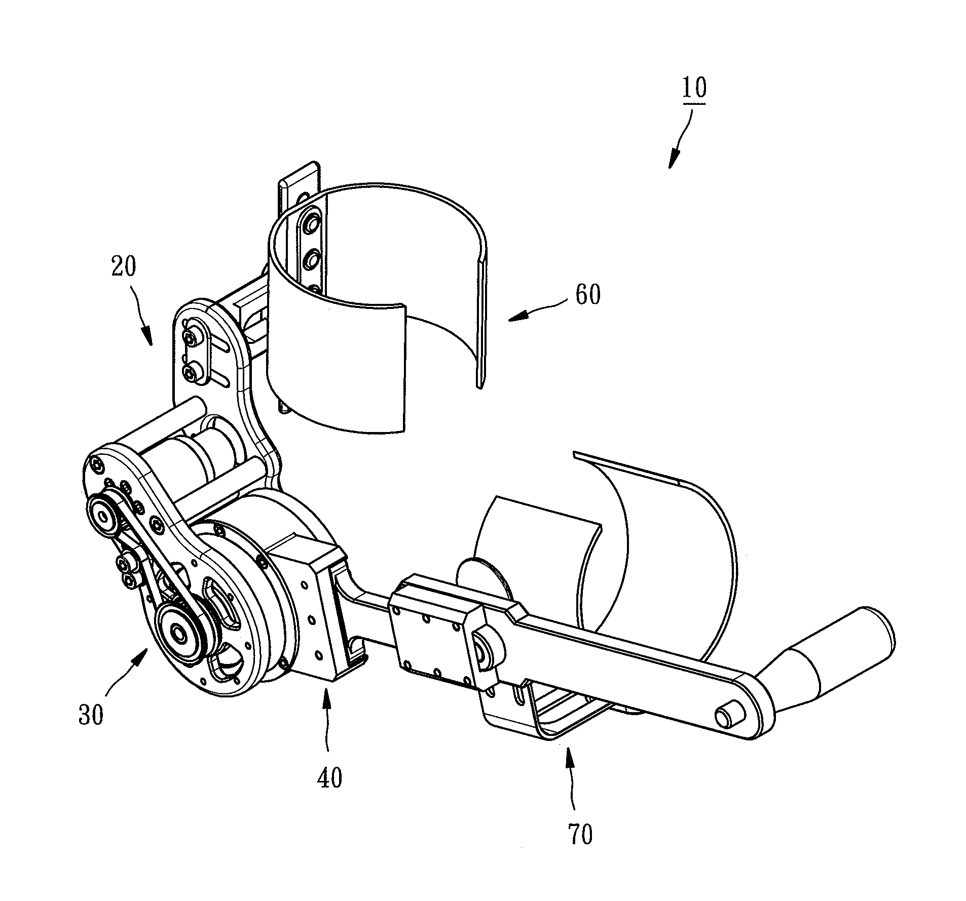
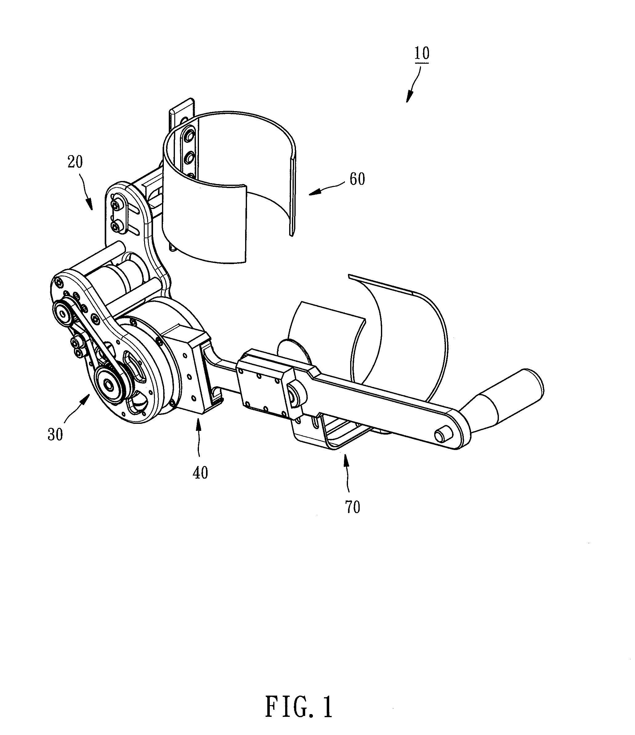
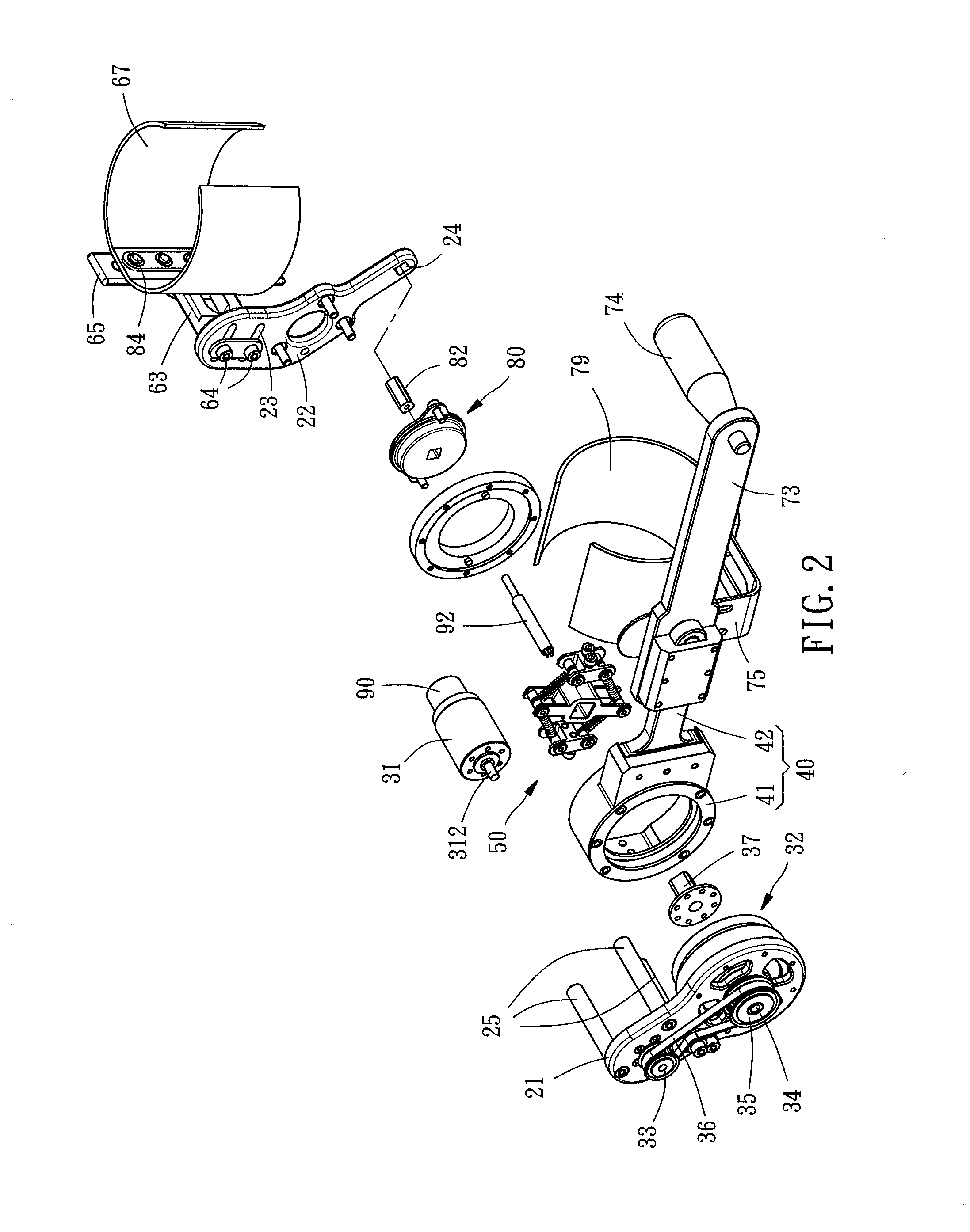
[0021]Referring to FIG. 1 and FIG. 2, a Force feedback type compliant orthotic device 10 of the present invention comprises a fixing base 20, a driving unit 30, a joint base 40, a resilience unit 50, a first limb supporting unit 60, and a second limb supporting unit 70.

[0022]The fixing base 20 has a first fixing board 21 and a second fixing board 22. The top end of the second fixing board 22 has two parallel X-axis adjustment slots 23. The bottom end of the second fixing board 22 has a rectangular hole 24. Upon completion of an assembly process, the first and second fixing boards 21, 22 are connected by three rods 25.

[0023]The driving unit 30 has a motor 31 and a decelerator 32. The motor 31 is fixed to the inner surface of the first fixing board 21 of the fixing base 20 and has a drive shaft 312. The drive shaft 312 passes through the first fixing board 21 to connect with a first transmission wheel 33. The decelerator 32 is disposed on the inner surface of the first fixing board 21...


PUM


Abstract

A Force feedback type compliant orthotic device includes a fixing base, driving unit, first limb supporting unit, and second limb supporting unit. The driving unit has a motor disposed at the fixing base and an output shaft connected to the motor. The output shaft is inserted into a joint base to connect with a resilience unit. The first limb supporting unit has a first supporting element fixed at the fixing base and a first electromyographic signal sensor disposed at the first supporting element. The second limb supporting unit has a second supporting element disposed at the joint base and a second electromyographic signal sensor disposed at the second supporting element. The motor generates appropriate auxiliary power according to the sensing result of the first and second electromyographic signal sensors, such that the first and second supporting elements move relative to each other precisely.

Description

BACKGROUND OF THE INVENTION[0001]1. Technical Field[0002]The present invention relates to rehabilitation aids, and more particularly, to a Force feedback type compliant orthotic device.[0003]2. Description of Related Art[0004]Patients with stroke, brain injury, or any other neurological injury usually need to undergo rehabilitation for a long period of time in order to restore the functions of their muscles and joints and preclude ensuing muscular dystrophy and joint degeneration.[0005]To free patients from dependence on a third party in receiving rehabilitation, conventional rehabilitation aids are developed and commercially available. For example, U.S. Pat. No. 8,211,042 discloses a magnetorheological damper and a friction brake for use in rehabilitation or for functioning as a prosthetic joint. However, U.S. Pat. No. 8,211,042 lacks any driving source and thus gives limited benefits to a user. Moreover, US2008 / 0071386 discloses an electromyographic signal sensor for use in making...

Claims


Application Information

Patent Timeline
Patent Type & Authority Applications(United States)
IPC IPC(8): A61H1/02
CPCA61H2230/605A61H1/02A61H1/0277A61H2201/1215A61H2201/1481A61H2201/165A61H2201/5069A61H2201/5092
Inventor WANG, REN-JENG
Owner HIWIN TECH
Learn More