System and device for mechanically extending and retracting landing gear of a semitrailer or a chassis

a technology of mechanical extension and retracting of landing gear, which is applied in the direction of wrenches, spanners, screwdrivers, etc., can solve the problems of exposing the operator to potential injuries, requiring significant time for the operator, and difficult use of manual jack structures, so as to reduce physical injuries, reduce parking space requirements, and raise and lower landing gear

Inactive Publication Date: 2015-06-25
JOHN L QUAID FAMILY PARTNERSHIP
View PDF7 Cites 3 Cited by
  • Summary
  • Abstract
  • Description
  • Claims
  • Application Information

AI Technical Summary

Benefits of technology

[0008]It is an object of this invention to provide an improved landing gear raising and lowering system using an adapter coupled with the existing gear reduction box assembly and a hydraulically powered, or an electrically powered, or pneumatic motor utilizing air from the vehicle's existing air pressure lines that extend to the brakes of the trailer which system operates in a simpler, smoother and far less complicated fashion to raise and lower the landing gear of a semi-trailer / chassis than prior art devices.
[0009]In the device of this invention, an adapter is mounted outboard of the gear reduction box assembly of the landing gear by means of a coupling. The adaptor assembly is lined with an elastic polymeric solid that flows like a liquid while under a load. This polymeric material has sufficient isolation and dampening characteristics to allow the use of an ordinary impact tool. Because of the characteristics of the polymer those power sources with an inherent pulsating drive can be used without any detrimental effect on the gear box assembly. The source of motive power is ideally (but is not limited to) obtained by tapping into the existing air brake line on the trailer / chassis unit to utilize the air pressure therein. The pneumatic, hydraulic or electrical drive assembly to power the rotation of the outboard shaft connected to the gear reduction box is then, at will and as needed, attached to the adapter on the outboard shaft. In one embodiment, the use of the gear reduction box assembly's outboard shaft with the adapter as placed on the output shaft of the gear reduction box assembly allows for the changing from high gear, to neutral, and to low gear in a simplified fashion. Built-in spring tension in the coupling maintains the unit in high gear until a change of gear is desired. Low gear can be obtained by a simple manual shifting.
[0012]It is therefore a still further object of this invention that the system of this invention be retrofitted onto existing trailer landing gear assemblies without impairing the operability of the prior art, manually operated systems already installed on the trailer. Thus, should the system of this invention fail for any reason, the manually operated former system can still be utilized to raise and lower the landing gear. This invention allows for the use of the manual system without having to remove the adaptor.
[0013]It is another object that the system of this invention can be installed on existing trailer landing gear systems without the need for rebuilding the entire landing gear system.
[0014]The system of this invention incorporates an ability to shift gears facilitating raising and lowering the legs of a trailer with a heavy load. The knob can be affixed to the crank shaft with a quick-release pin to allow changing of the knob back to a hand crank in the event that the user wishes to switch back to hand crank usage.
[0015]Also, the use of this device reduces physical injuries due to exertion caused by hand cranking. The use of this device also reduces parking space requirements since no space need be left for a user to hand crank the landing gear. The system of this invention, including its pneumatic impact / ratchet, is water-proof and very rugged, will operate in a very wide range of temperatures and is unaffected by freezing conditions. Further there is no shock or explosion hazard when using the system of this invention as is found in many of the prior art systems. Also, there is only a small number of components in the system of this invention in contrast to the rather complicated mechanical pneumatic actuators of the prior art. Moreover, the system of this invention is fully adapted for almost all existing landing gear systems, is lightweight and compact, and can be installed at a low cost.

Problems solved by technology

Manually operated jack structures are difficult to use, require significant time for the operator, and expose that operator to potential injuries as he or she is positioned next to the trailer / chassis while turning the crank to raise or lower the landing gear to in turn raise or lower the trailer / chassis.
These types of units, though, provide a pulsating drive that is not conductive to the desired smooth operation of raising and lowering the landing gear legs.
This pulsating drive is detrimental to the gear box assemblies as this pulse is transmitted through the connecting shaft to the gear assembly thereby potentially damaging the gears.
The landing gear of Gardner is not directly adjustable up and down by a gear system and cannot raise or lower the trailer.
The hydraulic system of Bach is large and cumbersome, and hydraulic pistons do not provide the same positive holding as provided by a gearing arrangement.
Power failure or loss of pressure could cause failure and collapse of the landing gear.
Because of the complexity and expense of prior art systems for raising and lowering semi-trailer landing gear, they have not been widely accepted in the trucking industry.
Also, because of the prior art's complexity and need for specialized parts, many of which have proven to be fragile, they have been generally unsuitable to the rugged demands of over-the-road semi-trailers in use of a daily basis.

Method used


Image

  • System and device for mechanically extending and retracting landing gear of a semitrailer or a chassis
  • System and device for mechanically extending and retracting landing gear of a semitrailer or a chassis
  • System and device for mechanically extending and retracting landing gear of a semitrailer or a chassis

Examples


Embodiment Construction

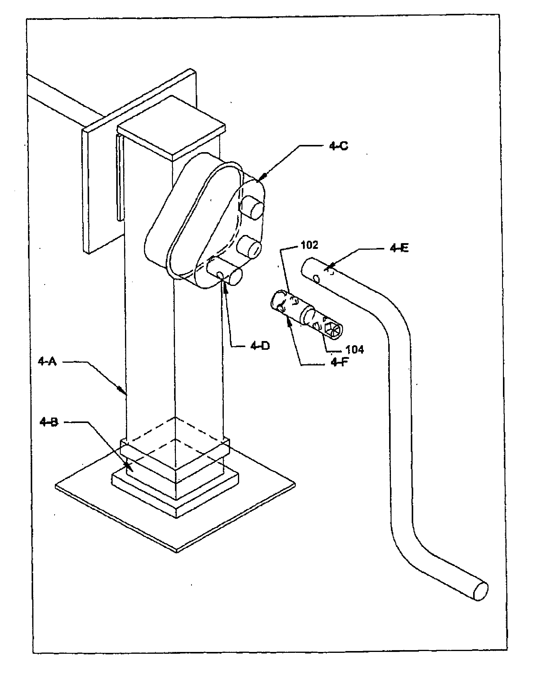
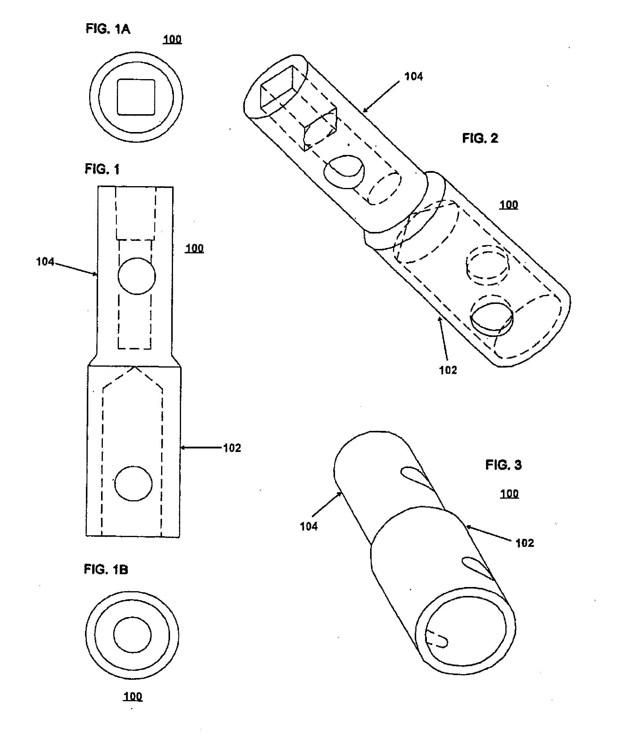
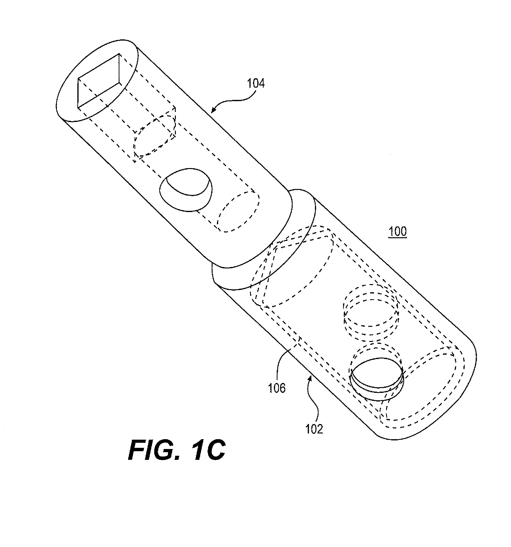
[0027]With reference to the figures, like reference characters will be used to indicate like elements throughout the several embodiments and views thereof. In particular, with reference to FIGS. 1, 1A, 1B, 2 and 3, the adapter 100 of the present invention is composed of a first connecting portion 102 and a second connecting portion 104. The first connecting portion 102 is designed to be connectable to the outboard shaft of a gear reduction box assembly or other gear mechanism for raising and lowering the landing gear of a trailer.

[0028]The second connecting portion 104 is formed to connect to a powered ratchet or other power tool / device designed to deliver powered, mechanical, hi-torque rotation, including but not limited to air impact tools, ratchet devices, other externally powered rotational devices.

[0029]In one embodiment, the adapter 100 is formed from machined carbon steel, ceramic material, or any such material that is of sufficient strength and is of such characteristics tha...


PUM


Abstract

The herein described system is used for mechanically extending and retracting a semi trailer's / chassis landing gear to support, raise or lower the trailer or chassis. Such system utilizes the existing apparatus minus the manual “crank” currently attached to the shaft which, in turn, is attached to the gear reduction box assembly. The manual crank is replaced with an “adapter” on the outboard shaft. The adaptor is lined with an elastic polymeric solid that flows like liquid under load. This adapter is then attached as needed to a pneumatic, hydraulic, or electrically powered device to turn the shaft thereby mechanically moving the landing / leveling legs into the desired position. The pneumatic device is powered by a connection inherent to the system attached to the semi-trailer or tractor's air brake line. The hydraulic device may be powered by an external hydraulic system. The electrical device may be DC battery powered or attached to an inverter in / or on the tractor.

Description

[0001]This is a continuation-in-part of application Ser. No. 12 / 458,501 filed on Jul. 14, 2009, which is hereby incorporated by reference in its entirety.BACKGROUND OF THE INVENTION[0002]1. Field of Invention[0003]The system of this invention resides in the arena of semi-trailer / chassis landing gear-extension, retraction and leveling mechanisms and more particularly relates to a power assisted mechanical system for the raising and lowering of a semi-trailer / chassis landing gear for positioning and / or raising or lowering the trailer or chassis.[0004]2. Description of Prior Art[0005]Many semi-trailers / chassis have front landing gear for support of the front of the trailer when the tractor is separated. These landing gear are generally two spaced apart, jack-type devices joined by a cross member with a common drive shaft engaged with a gear reduction box assembly. The gear reduction box assembly is driven by a manually operated crank. The gear reduction box assembly can have, and gener...

Claims


Application Information

Patent Timeline
Patent Type & Authority Applications(United States)
IPC IPC(8): B60S9/04B25B13/48
CPCB25B13/48B60S9/04B60S9/08
Inventor GRIFFIN, ADAM D.HUMPHRY, TERRY
Owner JOHN L QUAID FAMILY PARTNERSHIP
Why Eureka
Try Eureka