Bag supply apparatus

a bag supply and bag technology, applied in the direction of stacking articles, de-stacking articles, packaging goods types, etc., can solve the problems of complex drive mechanism, complicated operation of pull-up rods, and increased complexity of apparatuses, so as to reduce vibration and noise, simple and smooth

Active Publication Date: 2009-04-30
TOYO JIDOKI CO LTD
View PDF10 Cites 1 Cited by
  • Summary
  • Abstract
  • Description
  • Claims
  • Application Information

AI Technical Summary

Benefits of technology

[0027]As seen from the above, in the present invention, the rear edge of a bag bundle (or a single bag) on a conveyer is supported and lifted-up at its left and right sides by the bag supporting portions that are, respectively, continuously rotated or intermittently rotated in the same direction (in other words, without making reciprocating rotations or reciprocating movements) while maintaining the horizontal attitude. Accordingly, the motion of the bag supporting portions and the actuation mechanism therefor can be simple and smooth, the occurrence of vibration and noise can be reduced; and as a result, the bag supply apparatus of the present invention has high processing capability (with shortened time period for lifting up the bag(s) per incidence). In addition, since the bag supporting portions are provided so as to protrude in a horizontally inward direction from the left and right sides of the conveyer, the bag support members do not interfere with the feeding action of the bags, which is done while the rear edge of the bag bundle on the conveyer is being lifted up, onto the conveyer from the bag feeding device.
[0028]Furthermore, since the processing capability of the bag lifting device can be enhanced, the rear edges of bundles of bags on the conveyer can be lifted just as quickly as when the bags are fed to the conveyer one after another at a rapid pitch. As a result, the bundles of bags can be stacked automatically in such a format that an upper level bag on the conveyer is shifted in a forward direction, and the pitch (shift amount of the bags) can be kept constant.

Problems solved by technology

In the bag supply apparatus that uses the push-up rods, the push-up rods interferes with the pushing-in motion of the replenishing bag bundle; while in the bag supply apparatus that uses the pull-up rods, a complicated operation is involved for the pull-up rods that make a drive mechanism thereof more complicated as well.
In addition, in the bag supply apparatus of Japanese Patent Application Laid-Open (Kokai) No. 2004-210473, a 3-step operation is required to raise the rear edge of the bag bundle; and in the system that uses the push-up rods and the support arms makes the apparatus more complicated, while in the system that uses just the support arms, the actuation mechanism is more complicated.
Furthermore, the apparatuses in the above-described two related arts both involve reciprocating actions; and thus, these apparatuses are not suited for high-speed operation and unavoidably generate vibrations and noise when stopped.
However, the processing capability in the apparatuses described in the above-described two related arts, Japanese Patent Application Laid-Open (Kokai) Nos. 8-337217 and 2004-210473 is inadequate.

Method used


Image

  • Bag supply apparatus
  • Bag supply apparatus
  • Bag supply apparatus

Examples


Embodiment Construction

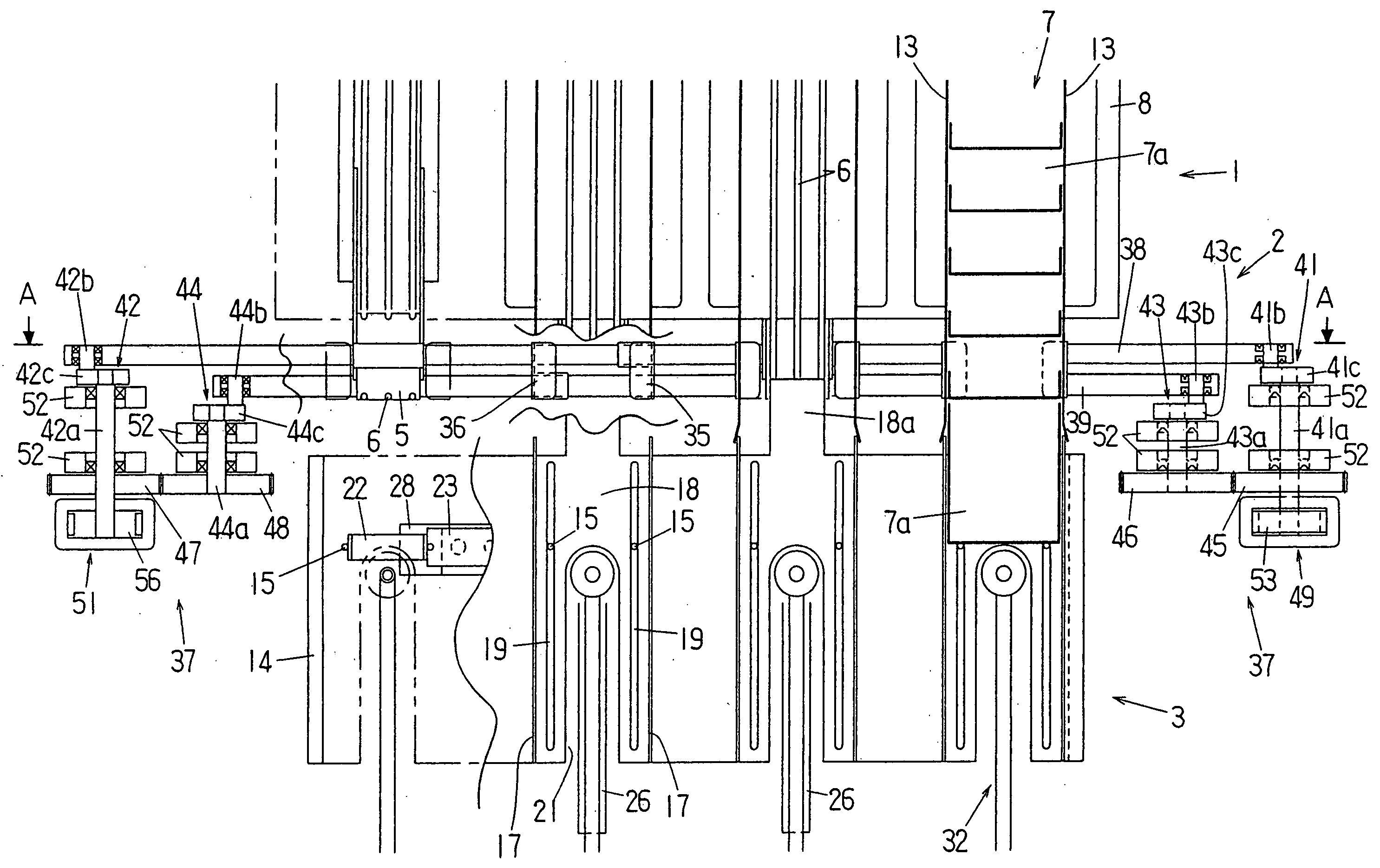
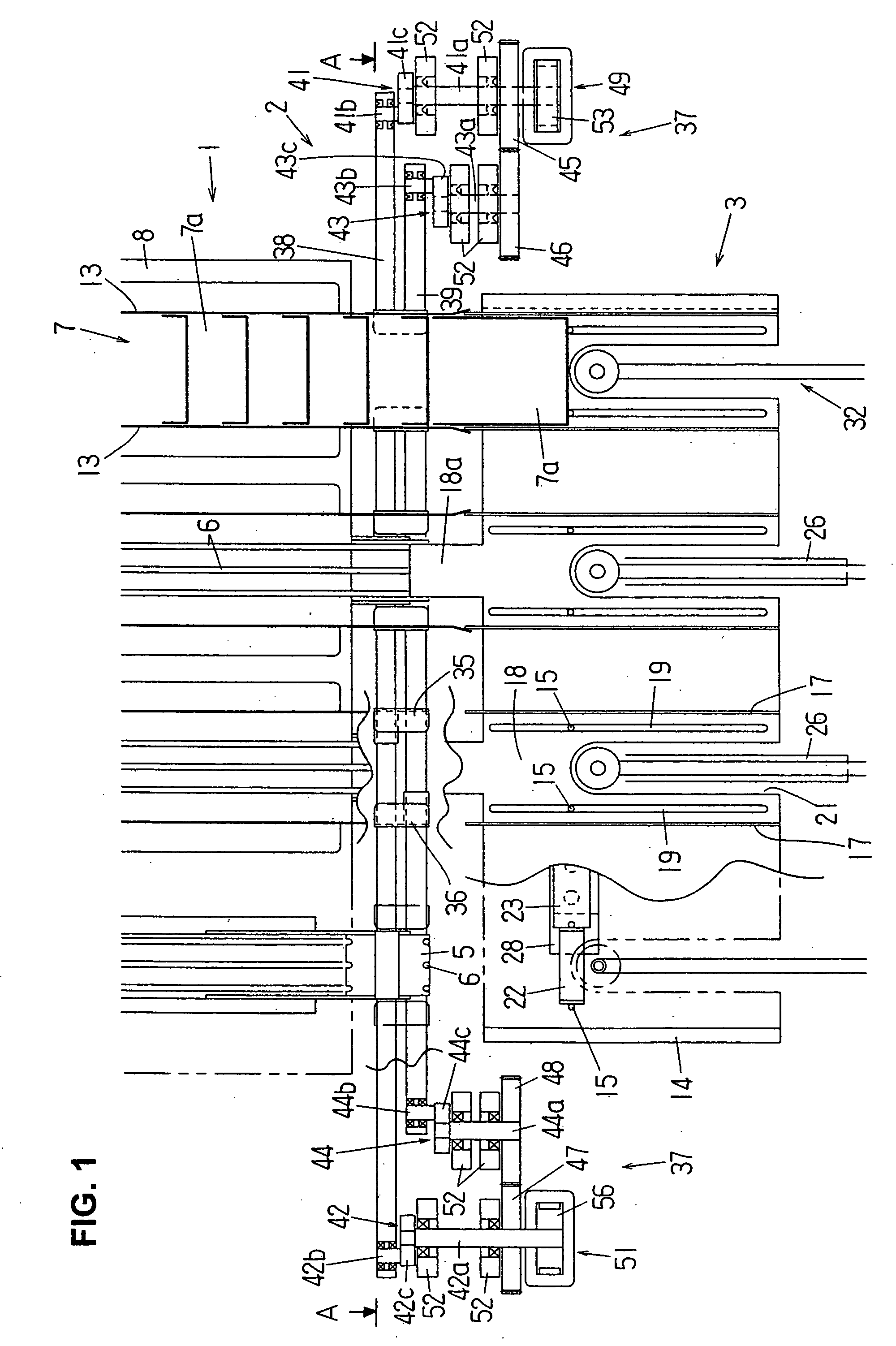
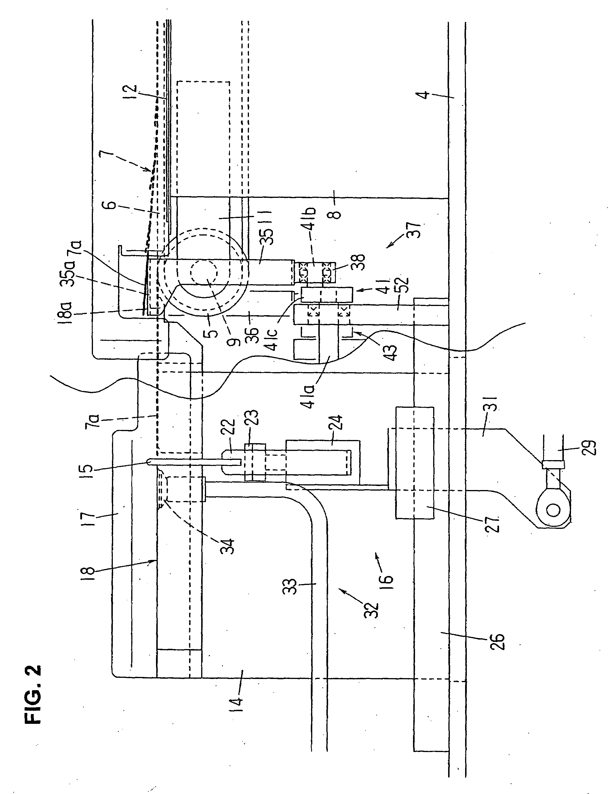
[0036]A bag supply apparatus according to the present invention will be described below in detail with reference to the accompanying drawings for FIGS. 1 through 7.

[0037]As shown in FIGS. 1 to 3, four (4) belt conveyors (also simply called “conveyer”) 1, which are a part of a conveyer magazine type bag supply apparatus, are provided in parallel. A bag lifting device 2 is provided at the proximity of the rear edges of the belt conveyors 1, and a bag feeding device 3 (more specifically, four bag feeding devices) is provided on the rear side of each one of the belt conveyors 1. All of these belt conveyors, the bag lifting device and the bag feeding devices are provided on a base platform 4 of the bag supply apparatus.

[0038]Each one of the belt conveyors 1 is comprised of a front-side pulley (or a drive pulley), which are not shown in the drawings, a rear-side pulley 5 (a driven pulley), and three (3) belts (round or endless belts) installed between these two pulleys. The belt conveyor ...


PUM

PropertyMeasurementUnit
rotational radiusaaaaaaaaaa
rotational speedaaaaaaaaaa
heightaaaaaaaaaa

Abstract

A bag supply apparatus for supplying bags onto a conveyer for transporting a bag bundle stacked such that an upper level bag is shifted forward, including a bag lifting device, which is provided with a pair of bag support members disposed facing one another on the left and right sides near the rear edge of a belt conveyor, and a rotation mechanism, which imparts translational motion of rotation in symmetric in a vertical plane with respect to the conveyance direction of the belt conveyor. The bag supporting portions of the bag support members contact the bag bundle from below to lift up the rear edge portion of the bag bundle and then separated from the bag bundle outwardly. While the bag supporting portions thus lifting the bag bundle, a new bag is fed into the space between the conveyance surface of the belt conveyor and the bag bundle.

Description

BACKGROUND OF THE INVENTION[0001]1. Field of the Invention[0002]The present invention relates to a bag supply apparatus for supplying bags to a conveyer for transporting a bag bundle stacked in such a format that the upper level bag is shifted in a forward direction and more specifically to a bag supply apparatus that supplies bags to a belt conveyor of a conveyer magazine type bag supply apparatus.[0003]2. Description of the Related Art[0004]A bag supply apparatus of the type described above is disclosed in, for instance, Japanese Patent Application Laid-Open (Kokai) Nos. 8-337217 and 2004-210473.[0005]In Japanese Patent Application Laid-Open (Kokai) No. 8-337217, a bag bundle (a group of bags stacked in a manner that the upper level bag is shifted in a forward direction with respect to the conveying direction of the belt conveyor of the bag supply apparatus) transported on the belt conveyor of a conveyer magazine type bag supply apparatus is transported forward; and when the bag b...

Claims


Application Information

Patent Timeline
Patent Type & Authority Applications(United States)
IPC IPC(8): B65G57/00B65B43/00
CPCB65B43/12B65H1/22B65H2701/191B65H29/6609B65H2404/67B65H1/30B65H29/6636
Inventor SETOZAKI, MASAKAZUYOSHIKANE, TOHRU
Owner TOYO JIDOKI CO LTD
Why Eureka
Try Eureka