Relay Valve Control Arrangement to Provide Variable Response Timing on Full Applications

a technology of relay valves and control arrangements, applied in the direction of braking systems, process and machine control, instruments, etc., can solve problems such as wheel lockup and/or abs activation

US20150175139A1Inactive Publication Date: 2015-06-25BENDIX COMML VEHICLE SYST LLC
16 Cites 4 Cited by

Patent Information

Authority / Receiving Office
US · United States
Patent Type
Applications(United States)
Current Assignee / Owner
Publication Date
2015-06-25
Estimated Expiration
Not applicable · inactive patent

Smart Images

  • Figure 1
    Figure 1
  • Figure 2
    Figure 2
  • Figure 3
    Figure 3
Patent Text Reader

Abstract

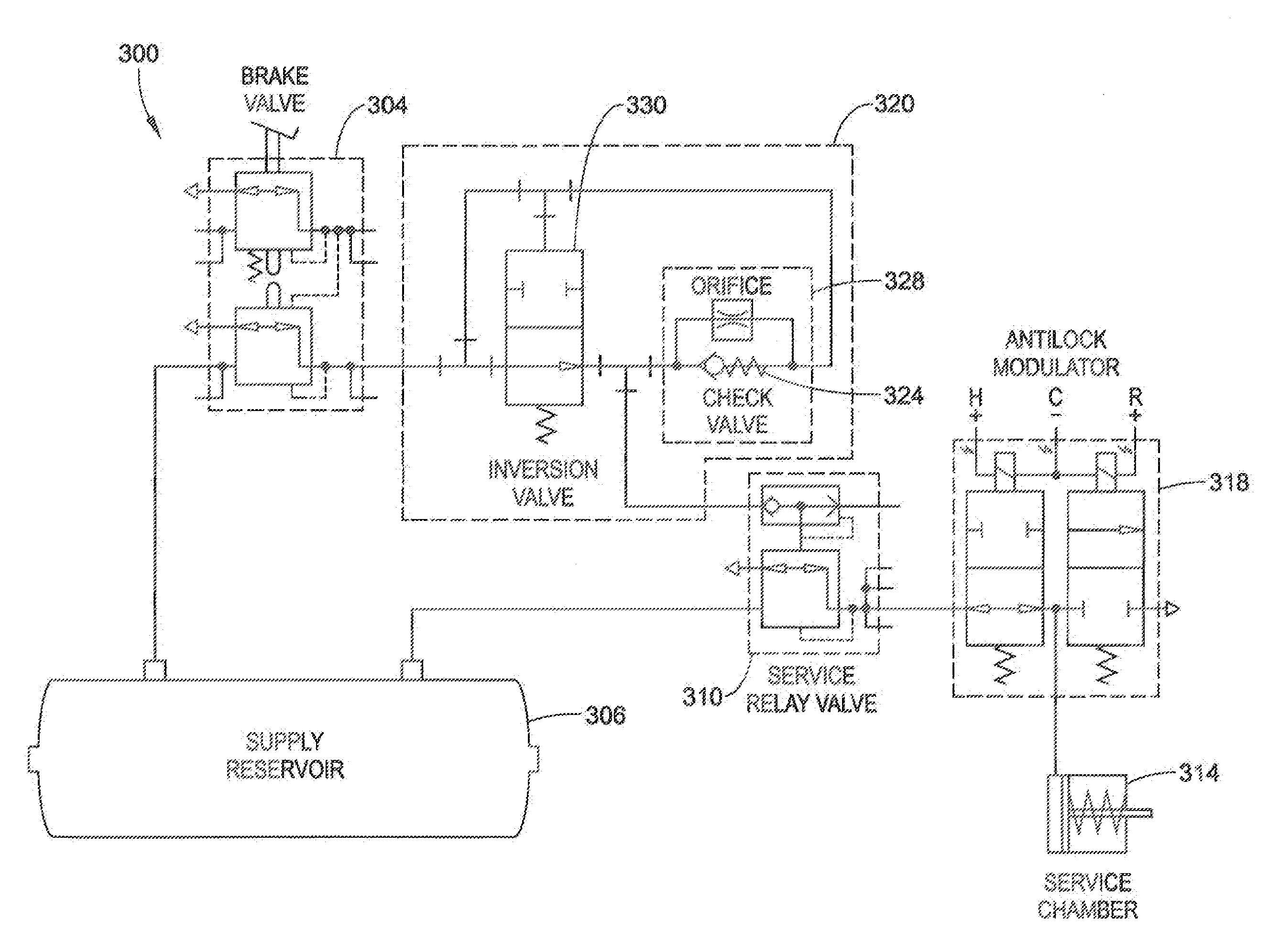
A brake system and related components including a metering device are configured to regulate a control signal received from a brake control device such that a control valve delays the supply of a level of requested braking pressure for a prescribed amount of time. The metering device can be an inversion valve and orificed check valve in a control circuit adapted to allow relatively unrestricted flow until a threshold pressure is reached, after which pressure the inversion valve closes and the flow is metered through an orifice. This has the effect of allowing rapid brake actuation to a first level, and then slowing further application of the brake until full requested braking is achieved. An electronic control unit can also be configured to regulate a control signal to delay development of the requested brake pressure.
Need to check novelty before this filing date? Find Prior Art

Description

CROSS-REFERENCE TO RELATED APPLICATIONS

[0001] The present application is a continuation of application Ser. No. 13 / 315,640 filed Dec. 9, 2011. The entire disclosure of the aforementioned application is herein expressly incorporated by reference.BACKGROUND

[0002] The present exemplary embodiment relates to controlling pressure systems. It finds particular application in conjunction with control arrangements for controlling pressure in pneumatically operated vehicle system, and will be described with particular reference thereto. However, it is to be appreciated that the present exemplary embodiment is also amenable to other like applications.

[0003] Air brake systems installed on large vehicles typically utilize pressurized air to operate the brakes of the vehicle. Prior art air brake systems usually include a combination of three different braking systems, namely: the service brakes, the parking brakes, and the emergency brakes. The service brake system applies and releases the brakes wh...

Examples

Embodiment Construction

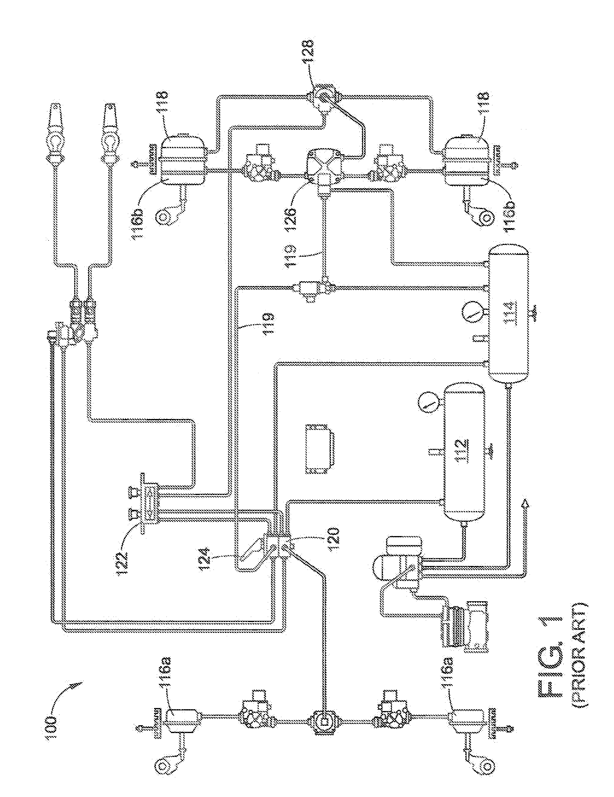
[0028]With reference to FIG. 1, an exemplary prior art air brake system is illustrated. The brake system 100 includes a primary air reservoir 112 (typically for supplying a rear brake circuit) and secondary air reservoir 114 (typically for supplying a front brake circuit). The primary and secondary air reservoirs 112, 114 supply pressurized air to apply a set of front service brake assemblies 116a and rear service brake assemblies 116b, and for releasing a set of spring brake assemblies 118. A set of air lines 119 communicate the pressurized air from the reservoirs 112, 114 to the brake assemblies 116a, 116b, and 118.

[0029]The air brake system 100 may also include a brake valve 120 and a parking control valve 122. The brake valve 120 includes a foot pedal 124, which opens the valve when the pedal is depressed. When open, the brake valve 120 allows pressurized air to flow from the reservoirs 112, 114 to a relay valve 126 for actuating the service brakes. The parking control valve 122...