Bearing device for crankshaft of internal combustion engine

a technology for internal combustion engines and bearings, which is applied in the direction of sliding contact bearings, machines/engines, rigid support of bearing units, etc., can solve the problems of increased mechanical loss of internal combustion engines, difficulty in providing oil to the sliding surface of halved bearings, and seizure, so as to increase the amount of oil to be supplied and reduce the amoun

Active Publication Date: 2018-01-11
DAIDO METAL CO LTD
View PDF0 Cites 0 Cited by
  • Summary
  • Abstract
  • Description
  • Claims
  • Application Information

AI Technical Summary

Benefits of technology

[0104]At the time of starting the internal combustion engine at cold temperature, oil whose viscosity becomes lower in the oil groove 42G in ±45° region θ1 of the upper-side halved bearing 42AU is early supplied to the inner circumferential surface 71 of the lower-side halved bearing 42L through the gap between the crush relief 70 on the rotationally forward side of the second journal portion 62 of the upper-side halved bearing 42AU on the rotationally forward side of the second journal portion 62 and the crush relief 70 on the rotationally backward side of the second journal portion 62 of the lower-side halved bearing 42L, and the surface of the second journal portion 62, from the circumferential end portion of the oil groove 42G on the rotationally forward side of the second journal portion 62 (in the direction of arrow X in FIG. 11), and the amount of oil to be supplied increased.
[0105]If the circumferential end portion of the oil groove 42G on the rotationally forward side of the second journal portion 62 does not communication with the crush relief 70 of the upper-side halved bearing 42AU on the rotationally forward side of the second journal portion 62 (beyond the scope of the present invention), the supply of oil to the inner circumferential surface 71 of the lower-side halved bearing 42L is delayed, and the amount of oil to be supplied is also reduced.

Problems solved by technology

Since the oil pump is operated by the rotational force of the crankshaft, the increase in the size of the oil pump is accompanied by an increase in mechanical loss of the internal combustion engine.
In cases where this bearing housing is used for the bearing device in JP 2006-125565 A, at the start of the internal combustion engine (in particular, at the time of starting from a state where the bearing device has a low temperature in cold areas), it is difficult to supply oil to the sliding surface of the halved bearing BL which is assembled into the bearing cap made of Fe alloy and which does not form an oil groove.
Thus, there is a problem in that seizure occurs on the inner circumferential surface of the halved bearing BL.
When the bearing gap is too large, axial runout occurs in the crankshaft, causing vibration and noise of the internal combustion engine.
Thus, oil does not easily flow out from the oil groove to the outside.
Therefore, oil is not supplied early to the inner circumferential surface of the other halved bearing BL assembled into the lower housing made of Fe alloy.

Method used


Image

  • Bearing device for crankshaft of internal combustion engine
  • Bearing device for crankshaft of internal combustion engine
  • Bearing device for crankshaft of internal combustion engine

Examples


example 1

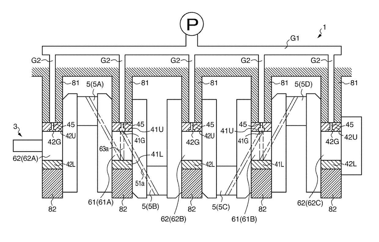
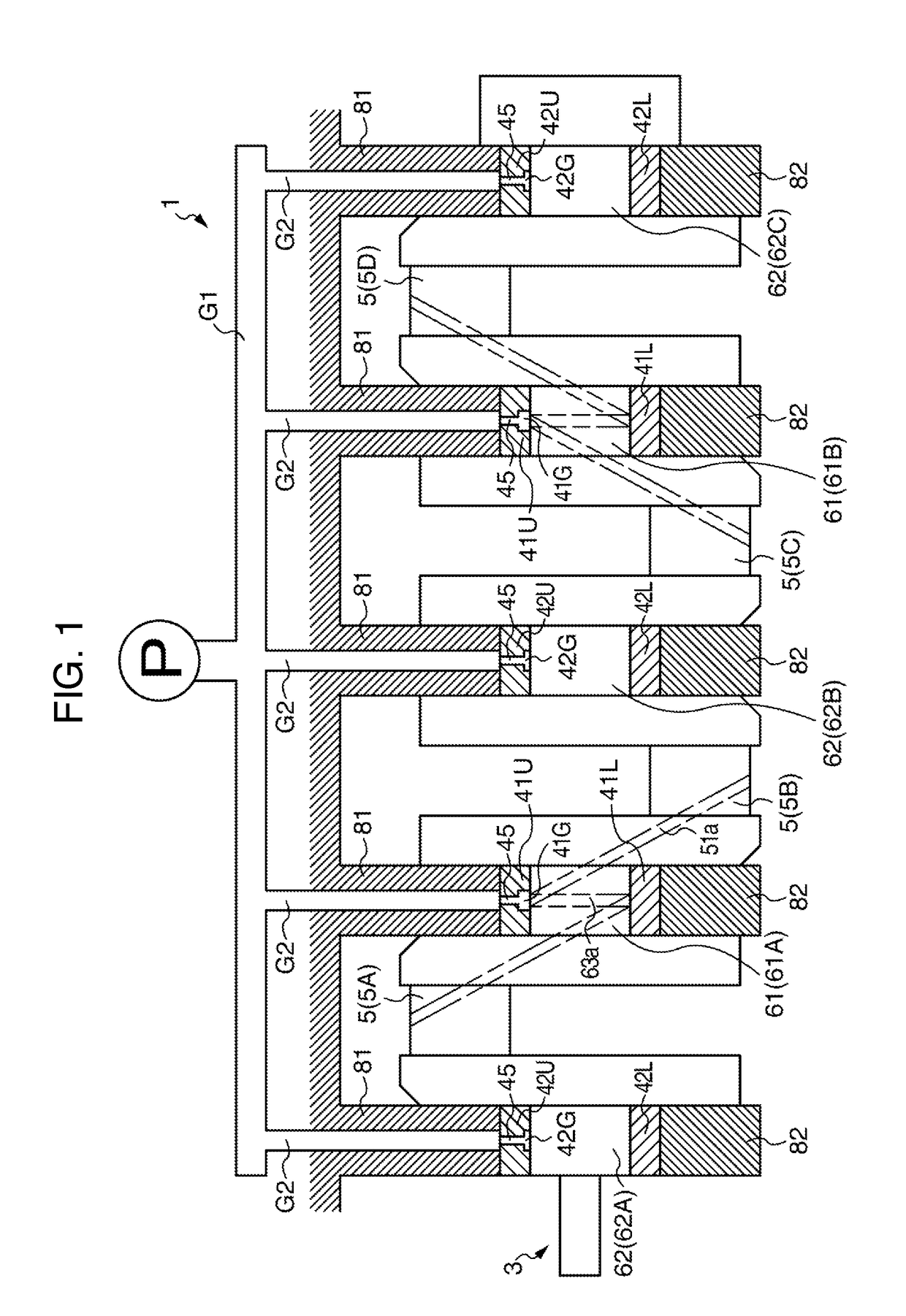
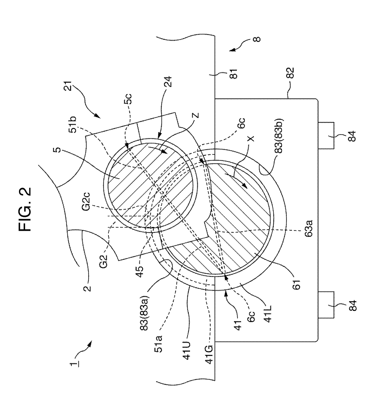
[0055]FIG. 1 is a schematic view of a bearing device 1 of the crankshaft 3 of the present invention as applied to an in-line four-cylinder internal combustion engine. FIG. 2 shows a bearing structure of journal portions 61 (No. 2 and No. 4 journal portions (61A, 61B) in FIG. 1) having a lubricating oil passage 63a for supplying oil to the crank pin portion 5 of the bearing device 1 shown in FIG. 1. (hereinafter, “journal portion with a lubricating oil passage” will be referred to as “first journal portion”) FIG. 3 shows a bearing structure of a journal portion 62 (No. 1, No. 3, and No. 5 journal portions (62A, 62B, 62C) in FIG. 1) without a lubricating oil passage for supplying oil to the crank pin portion 5 of the bearing device 1 shown in FIG. 1. (hereinafter, “journal portion without a lubricating oil passage” is referred to as “second journal portion”)

(Overall Configuration of Bearing Device)

[0056]As shown in FIG. 1, the bearing device 1 of the present example includes five jour...

example 2

[0101]Hereinafter, with reference to FIGS. 11 and 12, a second main bearing 42A which includes an upper-side halved bearing 42AU having a form which is different from Example 1 and for supporting the second journal portion 62 will be described. The description of portions which are same as or equivalent to those described in Example 1 is referred to by like numerals.

(Configuration)

[0102]First, the configuration will be described. The configuration of the first main bearing 41 for supporting the first journal portion 61 of this Example is the same as that of Example 1. The configuration of the second main bearing 42A is generally the same as that of Example 1 except for the shape of the oil groove 42G of the upper-side halved bearing 42AU.

[0103]Specifically, circumferential both end portions of the oil groove 42G of this Example is configured to communicate with the crush relief 70 and 70 at both end portions of the upper-side halved bearing 42AU in the circumferential direction.

(Eff...

example 3

[0106]Hereinafter, with reference to FIGS. 13 and 14, a second main bearing 42B which includes an upper-side halved bearing 42BU having a form which is different from Example 1 and 2, and for supporting the second journal portion 62 will be described. The description of portions which are same as or equivalent to those described in Example 1 and 2 is referred to by like numerals.

(Configuration)

[0107]First, the configuration will be described. The configuration of the first main bearing 41 for supporting the first journal portion 61 of this Example is the same as that of Example 1. The configuration of the second main bearing 42B is generally the same as that of Example 1 except for the shape of the oil groove 42G of the upper-side halved bearing 42BU.

[0108]Specifically, as shown in FIG. 13, the groove depth D2 of the oil groove 42G of this Example is configured to be minimum at the circumferential end face 72 of the oil groove 42G on the rotationally backward side of the journal por...


PUM


Abstract

The provided is a bearing device for a crankshaft of an internal combustion engine including: a crankshaft having a plurality of journal portions; main bearings for supporting the crankshaft; and a bearing housing, wherein a range in which the oil groove of the upper-side halved bearing of the second main bearing is formed in the circumferential direction includes at least a range of a circumferential angle of 20° within the ±45° region, a circumferential end portion of the oil groove on a rotationally forward side communicates with the crush relief at a minimum, and is open to a circumferential end face at a maximum, and a circumferential end portion of the oil groove on the rotationally backward side of the journal portion is positioned on a circumferential center portion side of the upper-side halved bearing from a circumferential end face of the upper-side halved bearing.

Description

INCORPORATION BY REFERENCE[0001]The present application claims priority from JP Patent Application Ser. No. 2016-134443 filed on Jul. 6, 2016, the content of which is hereby incorporated by reference into this application.BACKGROUND OF THE INVENTION1. Field of the Invention[0002]The present invention relates to a bearing device for a crankshaft of an internal combustion engine.2. Description of the Related Art[0003]A crankshaft of a multi-cylinder internal combustion engine has a plurality of journal portions and a plurality of crank pin portions. The plurality of journal portions includes a journal portion A with a lubricating oil passage (hereinafter simply referred to as “journal portion A”) for supplying oil to the crank pin portion and a journal portion B without a lubricating oil passage B (hereinafter simply referred to as “journal portion B”). The crankshaft is supported by a cylinder block lower portion of the internal combustion engine through a main bearing A in the journ...

Claims


Application Information

Patent Timeline
Patent Type & Authority Applications(United States)
IPC IPC(8): F16C19/14F16C3/04F16C33/66
CPCF16C19/14F16C33/6666F16C2204/10F16C2204/20F16C3/04F16C3/14F16C9/02F16C17/022F16C17/22F16C17/26F16C33/046F16C33/1055F16C33/1065F16C35/02F01M1/06F01M2001/062
Inventor UESU, YUSUKESAITO, YASUSHI
Owner DAIDO METAL CO LTD
Why Eureka
Try Eureka