
Infrared thermal sensor with good snr

Active Publication Date: 2015-06-25
MELEXIS TECH NV
View PDF1 Cites 18 Cited by
  • Summary
  • Abstract
  • Description
  • Claims
  • Application Information

AI Technical Summary

Benefits of technology

The patent aims to improve the performance of infrared thermal pixels, specifically in terms of signal-to-noise ratio.

Problems solved by technology

High vacuum devices typically provide larger signals, but require a more expensive sealing technique.

Method used


Image

  • Infrared thermal sensor with good snr
  • Infrared thermal sensor with good snr
  • Infrared thermal sensor with good snr

Examples


case 1 (

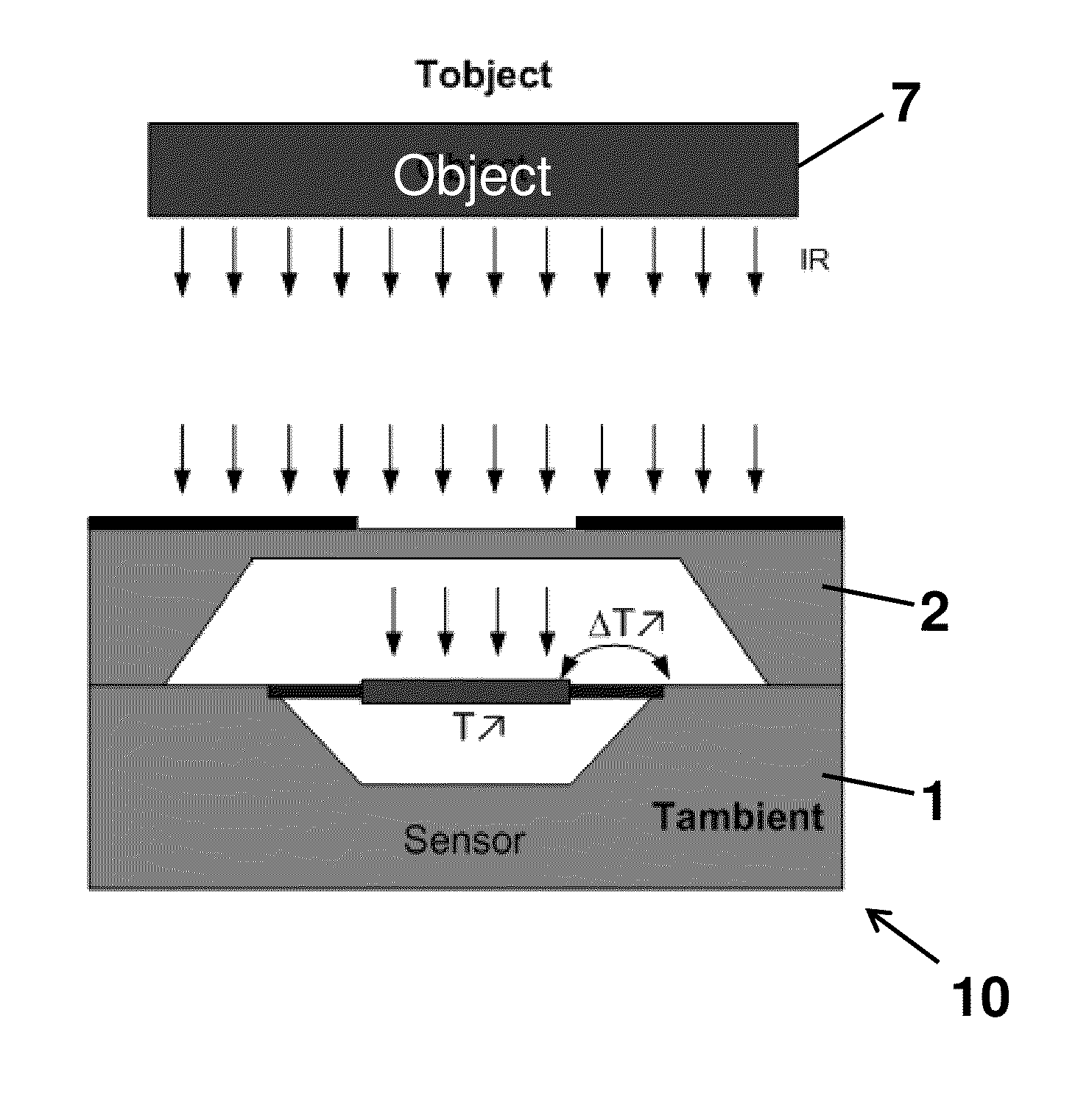
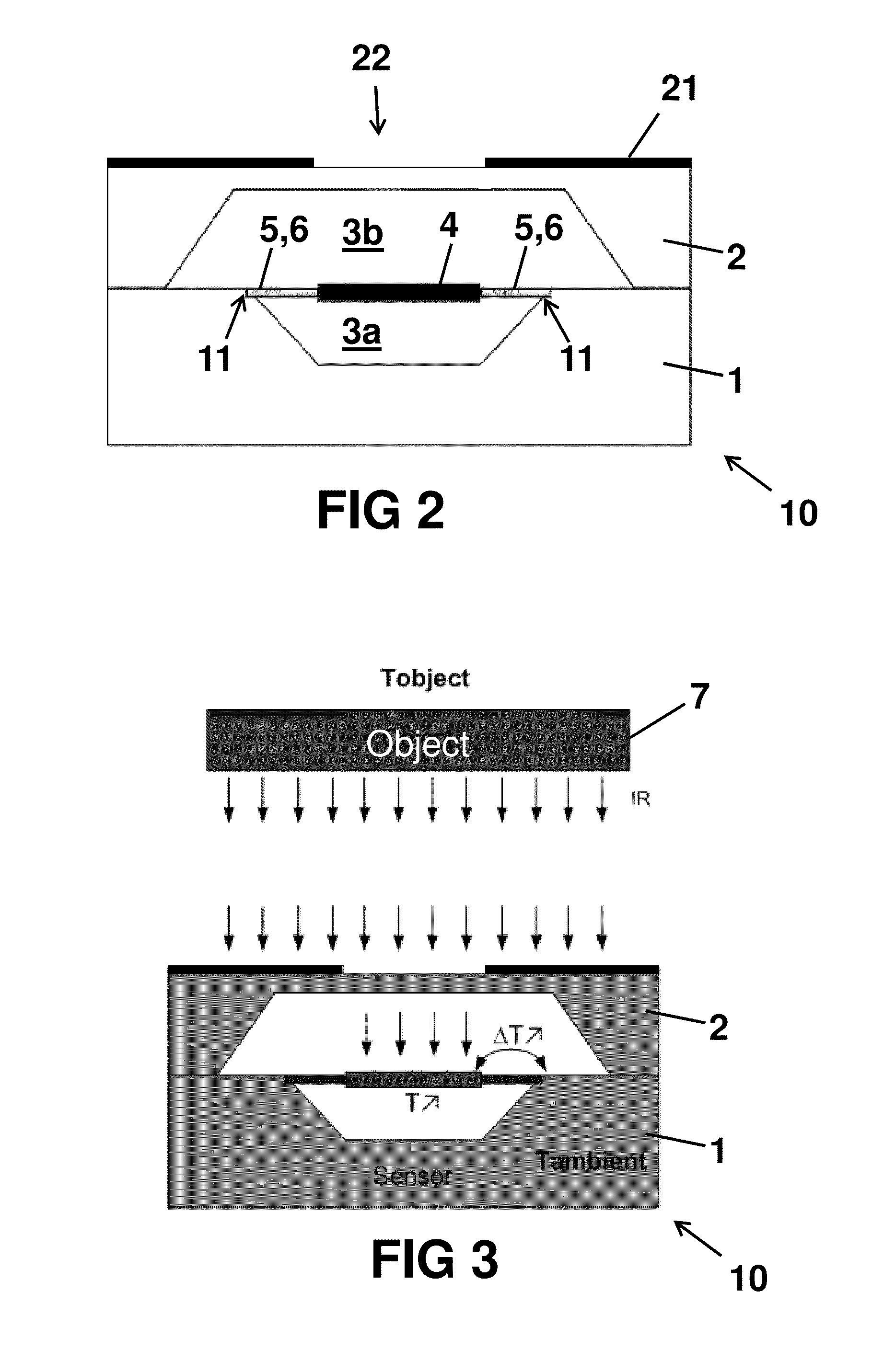
[0107small number of thermocouples): it is assumed that the thermal conduction of the air is dominant, that all the heat is lost through the air, and no heat is lost through the thermocouples. In this case, thermocouples can be added to the design without changing the temperature difference ΔT between the membrane and the silicon bulk. Since all the heat is lost through the air, adding or removing thermocouples will not change the temperature of the membrane. Thermocouples can be added as long as the thermal conduction of the air is dominant. From the moment that the thermal conduction through the air is not dominant anymore, the thermal conduction through the thermocouples will play a role and then this reasoning is not correct anymore. In that case, the temperature on the membrane will change when a thermocouple is added, since the thermal resistance from the membrane to the bulk is changed.

case 2 (

[0108large number N of thermocouples): it is assumed that the thermal conduction of the thermocouples is now dominant, that all the heat is lost through the N thermocouples, and that the heat loss through the air is negligible. Since all the heat is conducted through the N thermocouples, the thermal resistance between the membrane and the bulk increases proportional with the number of removed thermocouples. The temperature therefore also increases proportional with the number of removed thermocouples. This reasoning is true as long as the thermal conduction is dominated by the beams. When the thermal conduction is not dominated by the beams anymore, removing beams will not decrease the temperature anymore, because some heat is conducting through the air.

[0109]Looking at case 1 and case 2 it can be understood that there is an optimum somewhere between these two extremes. One might think that the optimum is reached where the heat dissipation through the beams (here: beam material+ther...


PUM

PropertyMeasurementUnit
Fractionaaaaaaaaaa
Pressureaaaaaaaaaa
Pressureaaaaaaaaaa

Abstract

An infrared thermal sensor for detecting infrared radiation, comprising a substrate and a cap structure together forming a sealed cavity, the cavity comprising a gas at a predefined pressure; a membrane arranged in said cavity for receiving infrared radiation; a plurality of beams for suspending the membrane; a plurality of thermocouples for measuring a temperature difference between the membrane and the substrate; wherein the ratio of the thermal resistance between the membrane and the substrate through the thermocouples, and the thermal resistance between the membrane and the substrate through the beams and through the gas is a value in the range of 0.8 to 1.2. A method of designing such a sensor, and a method of producing such a sensor is also disclosed.

Description

FIELD OF THE INVENTION[0001]The invention relates to the field of thermal infra-red sensors, more in particular to an infrared thermal sensor comprising a membrane suspended in a cavity by means of a plurality of beams.BACKGROUND OF THE INVENTION[0002]Thermal infrared sensors (also known as “infrared thermal pixels”, although this term is typically only used when an array of sensors is used) comprising a membrane (also known as “diaphragm”) suspended in a cavity by means of a plurality of beams (also known as “webs”) and having thermocouples arranged on said beams with one end located on the membrane and another end located on the substrate (also known as “bulk”), are known in the art.[0003]The membrane is typically chosen as large as possible for maximizing infrared light reception, the beams must be mechanically sufficiently strong for carrying the membrane, and are typically chosen as long and as small as possible for minimizing heat loss from the membrane through the beams towar...

Claims


Application Information

Patent Timeline
IPC IPC(8): G01J5/02G01J5/12
CPCG01J5/12G01J5/0225G01J5/023G01J5/024Y10T29/49002G01J5/02G01J5/0853
Inventor MAES, BENVAN BUGGENHOUT, CARLVAN DER WIEL, APPOLONIUS JACOBUS
Owner MELEXIS TECH NV
Features
  • Generate Ideas
  • Intellectual Property
  • Life Sciences
  • Materials
  • Tech Scout
  • Unparalleled Data Quality
  • Higher Quality Content
  • 60% Fewer Hallucinations
Learn More