Switching regulator and control circuit and control method therefor

Active Publication Date: 2015-06-25
SILERGY SEMICON TECH (HANGZHOU) CO LTD
View PDF13 Cites 24 Cited by
  • Summary
  • Abstract
  • Description
  • Claims
  • Application Information

AI Technical Summary

Benefits of technology

[0010]In view of this, one object of the present disclosure is to provide a switching regulator and a control circuit and a control method therefor.
[0011]According to one aspect of the present disclosure, there is provided a control circuit comprising a first controller and a second controller.
[0012]The first controller is configured to generate a first control signal for controlling a power switch in a power stage in accordance with a feedback voltage representing an output voltage of the power stage, a ripple signal and a reference voltage.
[0013]The second controller is configured to generate a second control signal with a predetermined frequency for controlling a rectifying switch in the power stage. Wherein, a duty cycle thereof varies with a difference between the feedback voltage and refe

Problems solved by technology

Thus, adopting different detection signals and/or control circuits may lead to different control effects on performance.
However, when t

Method used


Image

  • Switching regulator and control circuit and control method therefor
  • Switching regulator and control circuit and control method therefor
  • Switching regulator and control circuit and control method therefor

Examples


first embodiment

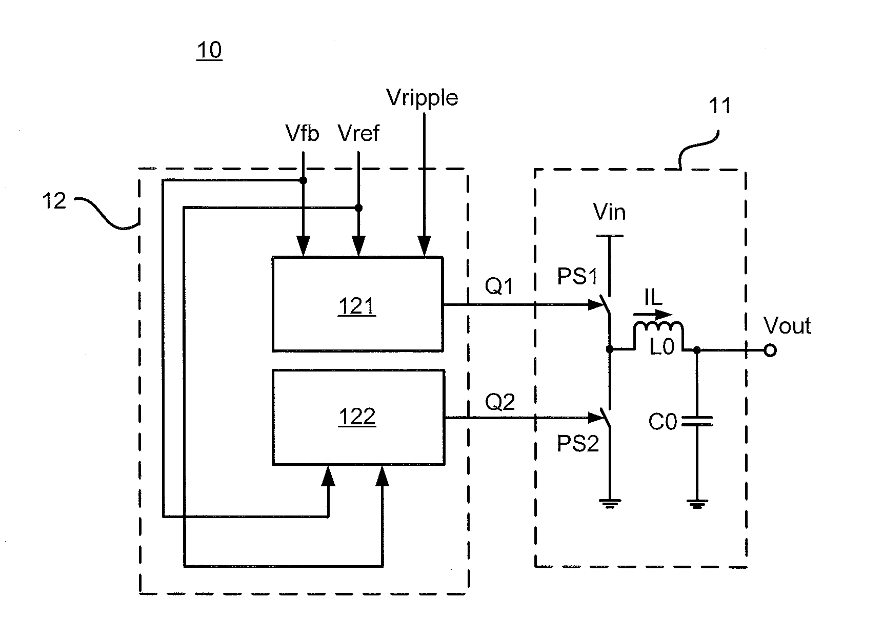
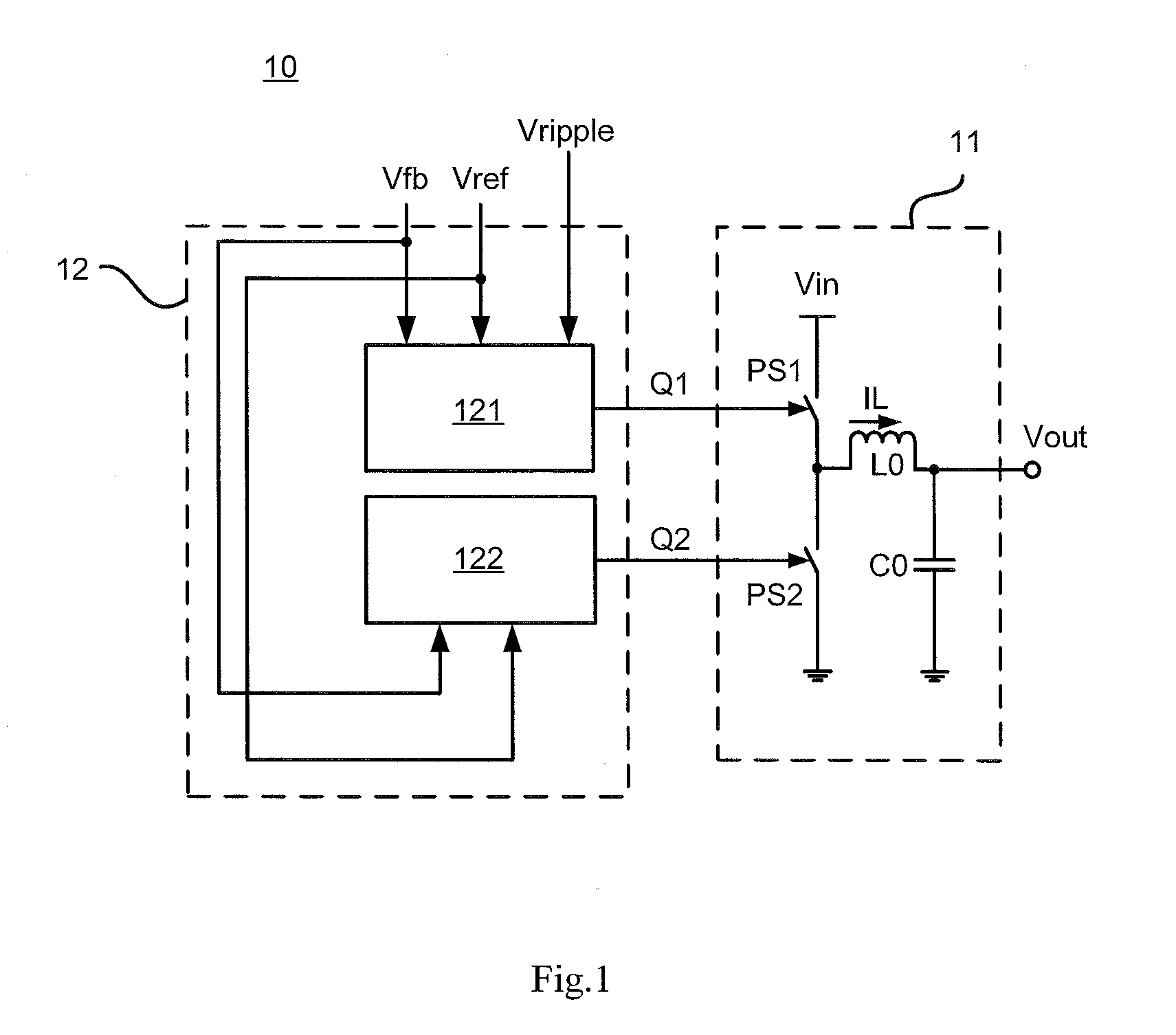
[0032]FIG. 1A is a schematic diagram of a switching regulator in accordance with the present disclosure. As shown in FIG. 1A, switching regulator 10 comprises power stage 11 and control circuit 12. Power stage 11 comprises power switch PS1, rectifying switch PS2, inductive element L0 and filtering element C0. In present disclosure, a power switch in a power stage refers to a switch which is turned on periodically so that power flows into the inductive element, and the energy is accumulated by the inductive element in a DC-DC regulator. A rectifying switch refers to a switch which is turned on periodically so that the power stored in the inductive element may flow to a load in a DC-DC regulator.

[0033]In the embodiment of the present disclosure, power switch PS1 may be any controlled semiconductor switching device, such as Metal-Oxide-Semiconductor Field Effect Transistor (MOSFET) and Insulated Gate Bipolar Transistor (IGBT) etc. Rectifying switch PS2 is electrically coupled to power ...

second embodiment

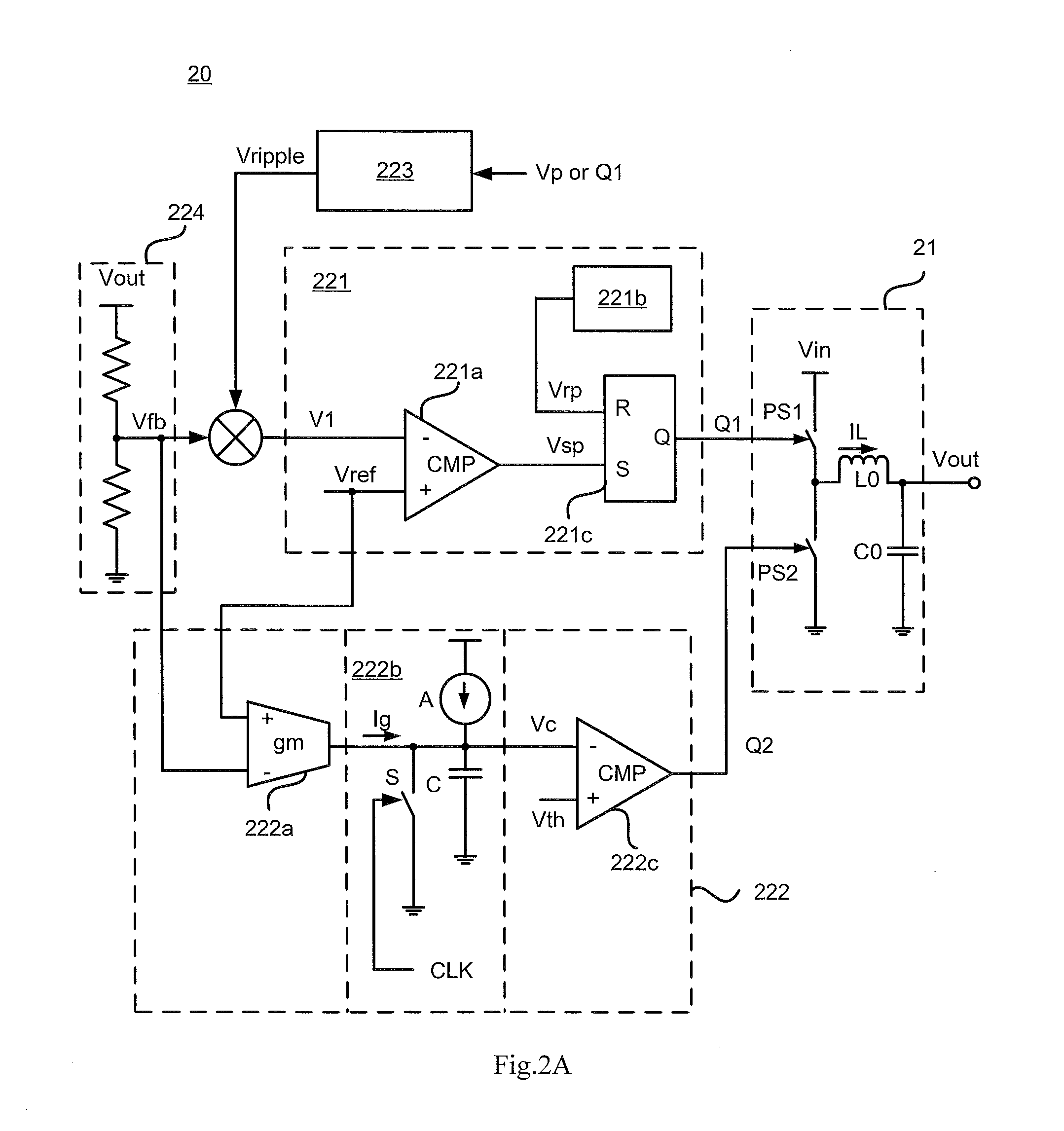
[0044]FIG. 2A is a schematic diagram of a switching regulator in accordance with the present disclosure. As shown in FIG. 2A, switching regulator 20 comprises power stage 21 and control circuit 22. Wherein, the structure of power stage 21 is substantially the same to that shown in FIG. 1, and will not be illustrated here. It is to be understood by those skilled in the art that power stage 21 may adopt well-known circuit topologies such as the buck topology and the boost topology as necessary.

[0045]Control circuit 22 comprises first controller 221 and second controller 222.

[0046]First controller 221 is configured to generate first control signal Q1 to control power switch PS1 in the power stage in accordance with feedback voltage Vfb, ripple signalVripple and reference voltage Vref. Wherein, feedback voltage Vfb is obtained in accordance with output voltage Vout of the power stage.

[0047]Ripple signalVripple is generated by any ripple generator well known by those skilled in the art. ...

third embodiment

[0067]FIG. 3A is a schematic diagram of a switching regulator in accordance with the present disclosure. As shown in FIG. 3A, switching regulator 30 in accordance with the embodiment of the present disclosure comprises power stage 31 and control circuit 32. Control circuit 32 comprises first controller 321 and second controller 322.

[0068]First controller 321 is configured to generate first control signal Q1 to control power switch PS1 in the power stage in accordance with feedback voltage Vfb and reference voltage Vref.

[0069]It is similar to the second embodiment that first controller 321 in the present embodiment may adopt various kinds of power switch controller well known by those skilled in the art, which will not be described herein.

[0070]Second controller 322 is configured to generate second control signal Q2 with a predetermined frequency to control rectifying switch PS2 in the power stage, and the duty cycle thereof varies in accordance with a difference between feedback vol...


PUM


Abstract

Disclosed are a switching regulator and a control circuit and a control method therefor. In one embodiment, by means of controlling a rectifying switch in a power stage with a second control signal which has a predetermined frequency and varies in accordance with the difference between a feedback voltage and a reference voltage, more energy may be shunted when a switching regulator operates in a light loaded or unloaded condition, so that audio noise is avoided.

Description

CLAIM OF PRIORITY AND CROSS-REFERENCE TO RELATED APPLICATION(S)[0001]This application claims the benefit of Chinese Patent Application No. 201310706484.7, filed on Dec. 19, 2013, which is incorporated herein by reference in its entirety.BACKGROUND OF THE INVENTION[0002]1. Field of the Invention[0003]The present disclosure relates to the field of power electronics, and particularly to a switching regulator and a control circuit and a control method therefor.[0004]2. Description of the Related Art[0005]A switching regulator typically comprises a power stage and a control circuit. The control circuit can consider variations in an input voltage, internal parameters and external loads, and may regulate the ratio of on / offtime of the switch system in the power stage, so that an output voltage or an output current of the switching regulator can be maintained as substantially constant. Therefore, the design of a particular control circuitry and approach is very important to the overall perf...

Claims


Application Information

Patent Timeline
IPC IPC(8): G05F1/56H02M3/158
CPCH02M3/158G05F1/56H02M3/1588H02M1/0032Y02B70/10
Inventor YUAN, XIAOLONG
Owner SILERGY SEMICON TECH (HANGZHOU) CO LTD
Why Eureka
Try Eureka