Device control method and computer-readable recording medium

Inactive Publication Date: 2015-06-25
SOVEREIGN PEAK VENTURES LLC
View PDF9 Cites 16 Cited by
  • Summary
  • Abstract
  • Description
  • Claims
  • Application Information

AI Technical Summary

Benefits of technology

[0012]According to the present disclosure, a further improvement can be achieved. These general and specific aspects may be

Problems solved by technology

However, the background art described abov

Method used


Image

  • Device control method and computer-readable recording medium
  • Device control method and computer-readable recording medium
  • Device control method and computer-readable recording medium

Examples


Example

First Embodiment

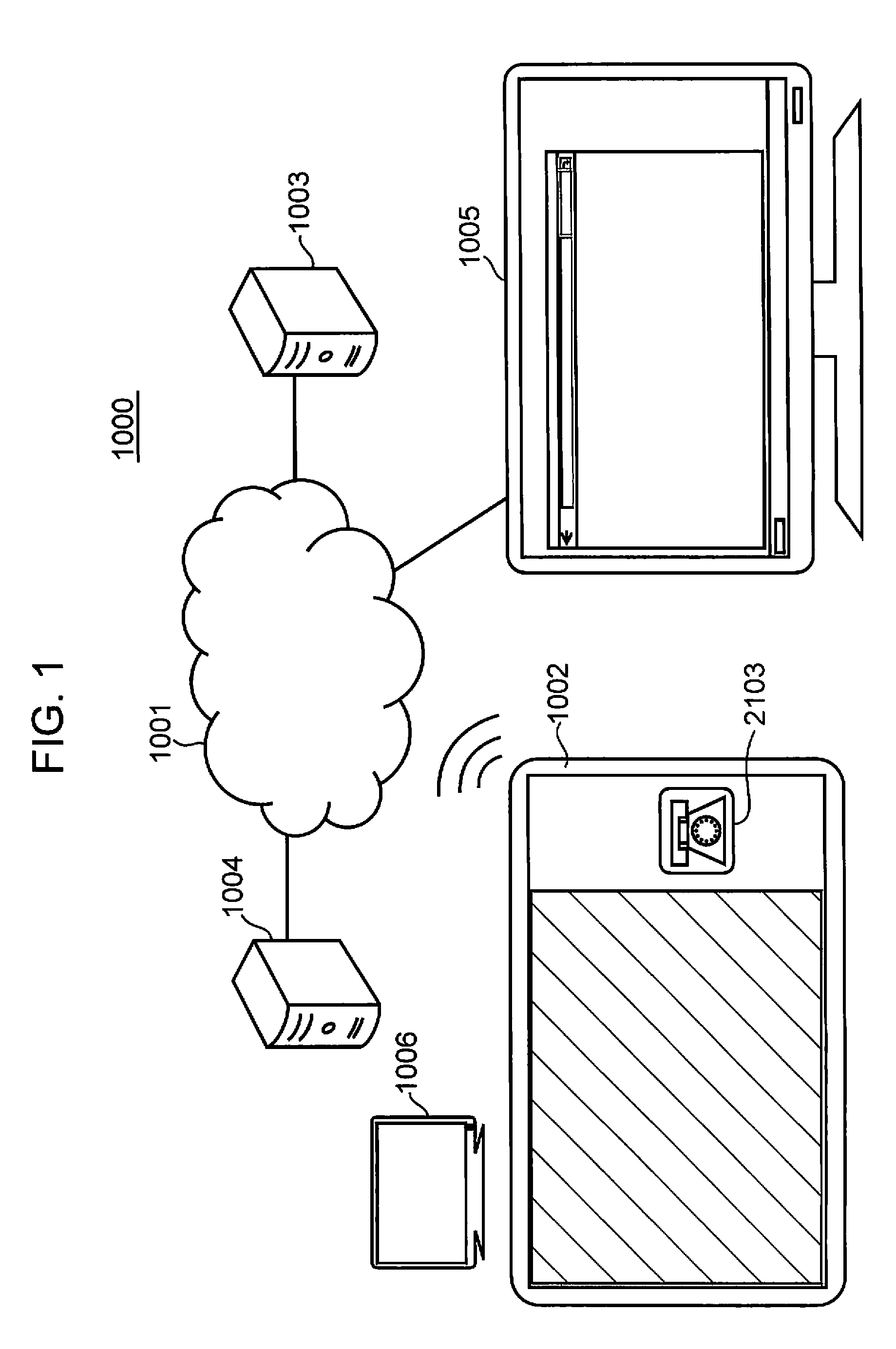
[0162]FIG. 1 is a diagram showing an overall configuration of a remote support system 1000 according to a first embodiment of the present disclosure. As shown in FIG. 1, the remote support system 1000 includes a user mobile terminal 1002, a cloud server 1003, a call-response control server 1004, and an operator operation terminal 1005. The user mobile terminal 1002, the cloud server 1003, the call-response control server 1004, and the operator operation terminal 1005 are connected via an external network 1001 such as the Internet so as to be capable of communicating with each other.

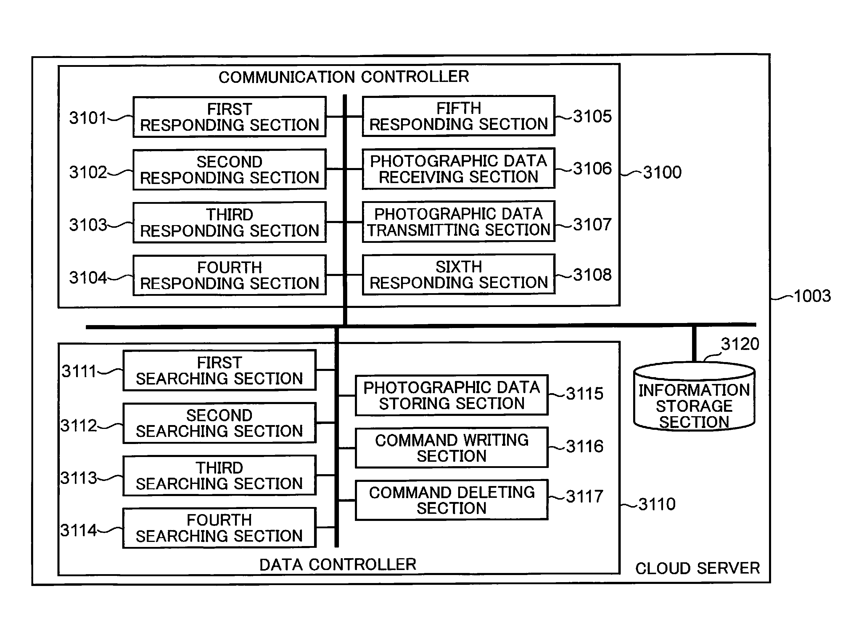
[0163]A mobile information apparatus such as a smartphone and a tablet is adopted as the user mobile terminal 1002. However, these are merely examples and a button type mobile information apparatus such as a mobile phone may be adopted as the user mobile terminal 1002. The cloud server 1003 is arranged at a cloud center. The cloud server 1003 mediates exchange of data, commands, and the li...

Example

Second Embodiment

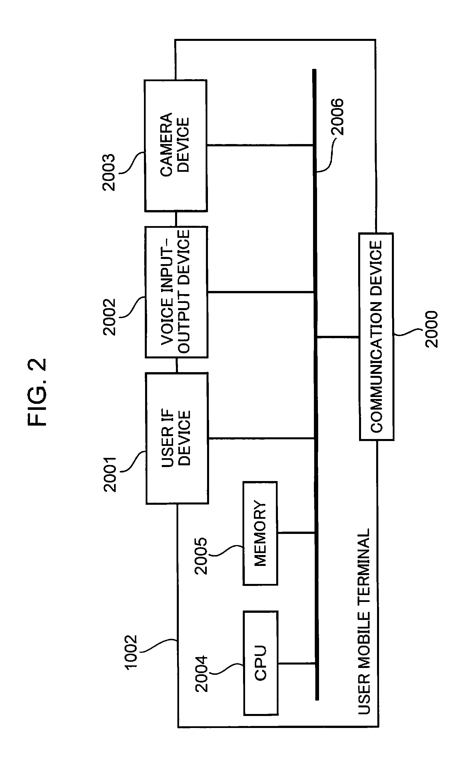
[0271]FIG. 24 is a diagram showing functional blocks of the user mobile terminal 1002 according to the second embodiment of the present disclosure. A configuration of the remote support system 1000 according to the second embodiment is the same as that according to the first embodiment shown in FIG. 1. In addition, a configuration of the user mobile terminal 1002 according to the second embodiment is the same as that according to the first embodiment shown in FIG. 2. Furthermore, configurations and functional blocks of the cloud server 1003, the call-response control server 1004, and the operator operation terminal 1005 according to the second embodiment are the same as those according to the first embodiment shown in FIGS. 4 to 9.

[0272]As shown in FIG. 24, the remote support application 2100 of the user mobile terminal 1002 according to the second embodiment includes a hash value comparing section 2200 as a functional block. The third user acquiring section 2104 ac...

Example

Third Embodiment

[0289]FIGS. 30 and 31 are diagrams showing sequences according to a third embodiment of the present disclosure. FIG. 30 shows a sequence up to start of a telephone conversation, and FIG. 31 shows a sequence including and subsequent to the start of a telephone conversation. A configuration of the remote support system 1000 according to the third embodiment is the same as that according to the first embodiment shown in FIG. 1. Furthermore, configurations and functional blocks of the user mobile terminal 1002, the cloud server 1003, the call-response control server 1004, and the operator operation terminal 1005 according to the third embodiment are the same as those according to the first embodiment shown in FIGS. 2 to 9.

[0290]In FIG. 30, steps 8001 to 8004 are the same as steps 8001 to 8004 according to the first embodiment shown in FIG. 10.

[0291]FIG. 32 is a diagram showing an example of a user access destination information table 9701 of the cloud server 1003 accordi...


PUM


Abstract

A method in a communication system in the present disclosure includes: receiving a first access from the information apparatus which starts a first application for a telephone conversation function; transmitting an identifier and a confirmation destination address to the information apparatus in response to the first access; receiving an instruction to the information apparatus from the information processing apparatus; receiving a second access using the confirmation destination address from the information apparatus; transmitting the instruction to the information apparatus in response to the second access; and when it is judged that the instruction instructs the information apparatus to start the second application for providing a camera function, causing the information apparatus to continue the telephone conversation process, to start the second application without involving a user operation, receiving image information captured using the camera function from the information apparatus, and forwarding the image information to the information processing apparatus.

Description

TECHNICAL FIELD[0001]The present disclosure relates to a device control method and a computer-readable recording medium.BACKGROUND ART[0002]Patent Document 1 relates to a service system in which an operator searches for a destination on behalf of a user of a mobile phone. Specifically, when an application named “EZ Koban” is started on a display screen of a mobile phone 1, the mobile phone 1 acquires a current position of the mobile phone 1 from a GPS apparatus 3 (FIG. 4). Next, the application is interrupted and a call is made by the mobile phone 1 to a service center of an operator (FIG. 4). In a telephone conversation with the user via the mobile phone 1, the operator orally confirms a destination of the user. The operator searches for map information from a current position of the mobile phone 1 to a destination and registers the map information in an EZ Koban server 4 (FIG. 5). The user of the mobile phone 1 ends the telephone conversation with the operator, restarts the applic...

Claims


Application Information

Patent Timeline
IPC IPC(8): H04L29/08H04M1/72445
CPCH04L67/02H04L67/104H04M3/493H04M1/72445
Inventor TAKAGISHI, SATORU
Owner SOVEREIGN PEAK VENTURES LLC
Why Eureka
Try Eureka