Battery and control module for both energizing and controlling a powered surgical tool that is releasably attached to the module

Active Publication Date: 2015-07-02
STRYKER CORP
View PDF12 Cites 38 Cited by
  • Summary
  • Abstract
  • Description
  • Claims
  • Application Information

AI Technical Summary

Benefits of technology

This patent describes a new and improved powered surgical tool assembly that is designed to be lightweight and minimize stress on the surgeon using the tool. The tool is connected to a battery unit, which is also lightweight, to provide power. The tool is made in a way that it can be easily attached to other tools and includes a motor that is powered by the battery. The assembly is easy to assemble and use, with sensors that provide accurate position data for the motor. The charger to which the battery is connected can also perform other tasks, such as testing the tool unit controller to ensure it is properly functioning. Overall, this invention provides a tool assembly that is easy to use and reduces stress on the practitioner.

Problems solved by technology

Specifically, when pulled or tangled during the surgical procedure, the cord can become unsterilized, can be pulled from the hands of the user, and can be fully or partially disconnected from a power socket thereby ceasing operation of the instrument and / or creating a potential for electrically shocking the patient.
Also, the cord is prone to increased failure relative to other components of the instrument when subjected to steam sterilization, such as with an autoclave.
However, to date, it has proven difficult to provide a motorized battery powered motorized surgical tool that outputs power in the range of 25 to 125 Watts.

Method used


Image

  • Battery and control module for both energizing and controlling a powered surgical tool that is releasably attached to the module
  • Battery and control module for both energizing and controlling a powered surgical tool that is releasably attached to the module
  • Battery and control module for both energizing and controlling a powered surgical tool that is releasably attached to the module

Examples


first embodiment

I. First Embodiment

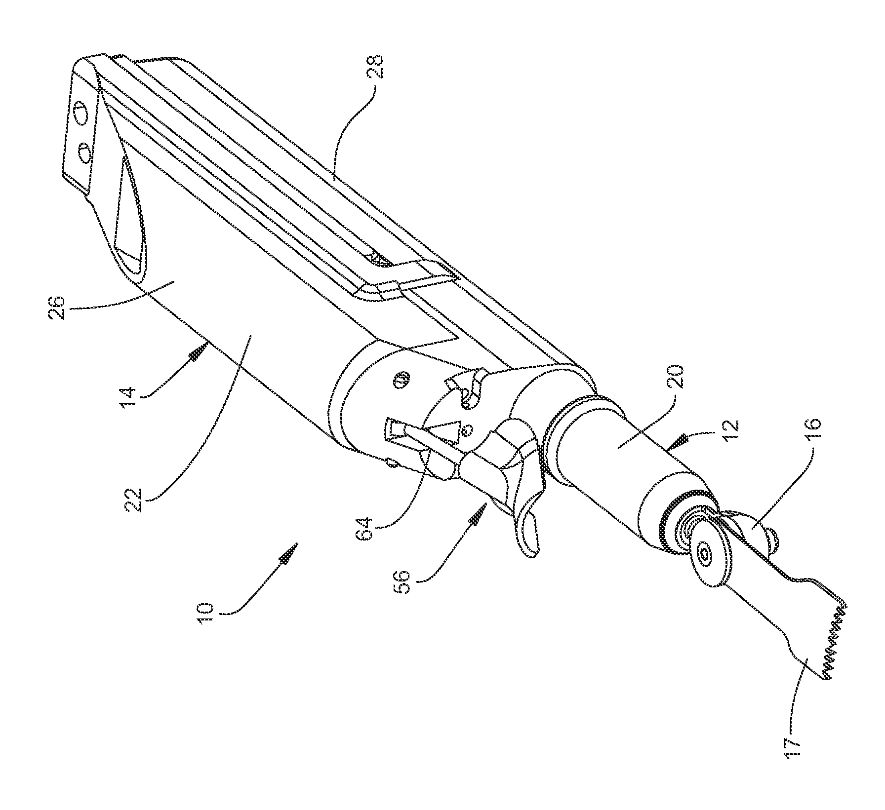
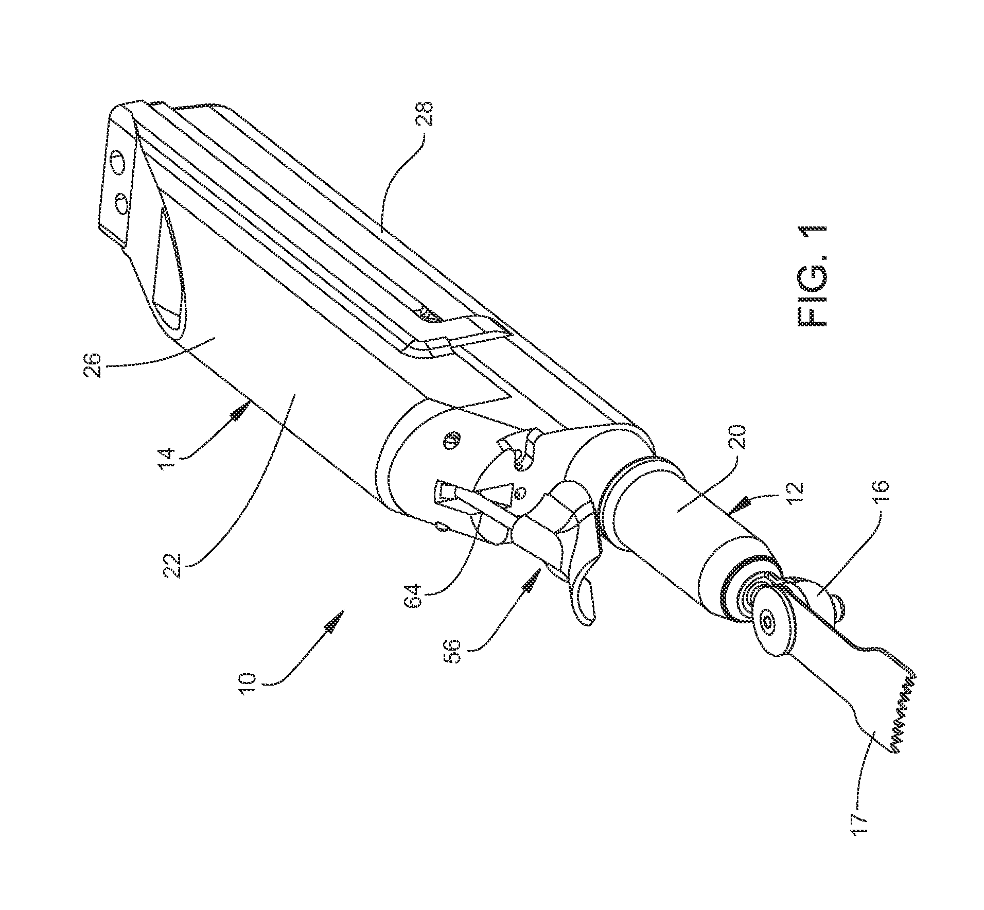
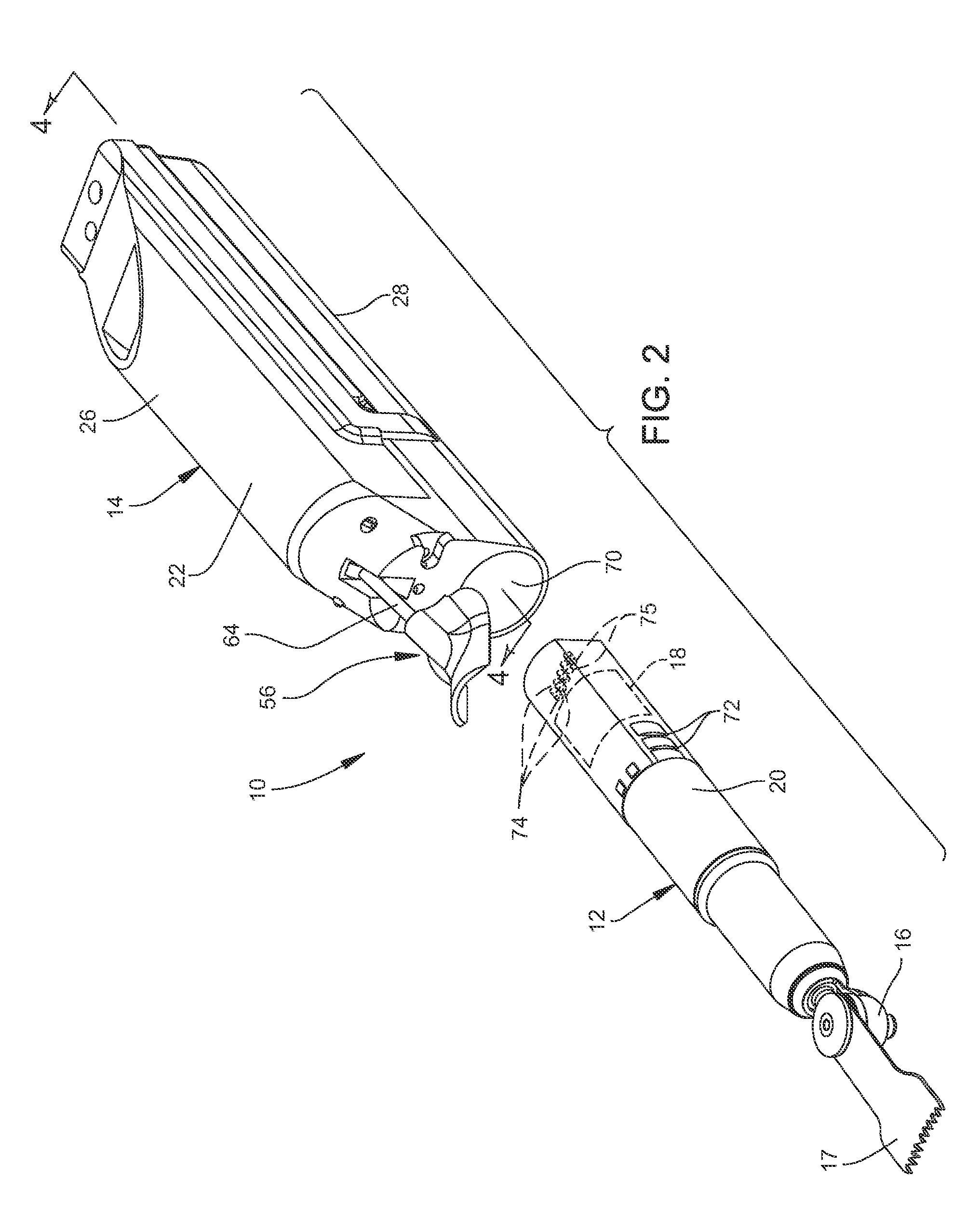
[0101]Referring to the Figures, wherein like numerals indicate like parts throughout the several views, a powered surgical tool assembly 10 is generally shown for use in surgical procedures such as orthopedic surgery. In certain embodiments, the surgical tool assembly has a pencil-grip configuration to allow a user to hold and grip the surgical tool assembly like a pencil. With reference to FIGS. 1 and 2, the surgical tool assembly 10 includes a tool unit 12 and a battery and control module 14. Battery and control module (BCM) 14 releasably engages the tool unit 12. The BCM 14 provides the power that energizes the tool unit 12. Battery and control module 14 also controls the application of the energization signals to the tool unit 14.

[0102]The representative tool unit 12 shown in FIGS. 1 and 2 is a sagittal saw configured to hold and drive an energy applicator 17. Here energy applicator 17 is a sagittal saw blade for cutting bone, ligaments, or other tissue. The s...

second embodiment

II. Second Embodiment

A. Overview

[0155]An alternative powered surgical tool assembly 120 of this invention is now generally described by reference to FIGS. 17-19. Powered surgical tool assembly 120 includes a tool unit 124 that is removably attached to a battery and control module 128. The illustrated tool unit 124 includes a motor 950 as a power generating unit. The particular tool unit is designed to oscillate a sagittal saw blade 17. Internal to BCM 128 are two rechargeable cells 38. Cells 38 provide the power for energizing the tool unit motor 950. Also internal to the tool unit 128 is a tool unit controller 530 (FIG. 45). The tool unit controller 530 regulates the application of energization signals from cells 38 to the tool unit motor 950. A switch 440 is moveably mounted to the BCM 128. Tool unit controller 530 includes a sensor that monitors the manual actuation of switch 440. In part, in response to the actuation of the switch 440, the tool unit controller controls the appli...

third embodiment

III. Third Embodiment

[0337]FIGS. 64-66 depict the basic structure of an alternative battery and control module 1200 of this invention. Battery and control module 1200 has a housing or body that is pistol shaped. Thus the housing includes an approximately shape barrel 1202. The housing has a grip portion 1204 that extends downwardly from the barrel. Internal to the barrel 202 is the nacelle 1256 in which the tool unit, such as tool unit 124, is releasably seated. Rechargeable cells 38 for energizing the tool unit 124 are disposed in grip portion 1204.

[0338]Battery and control module 1202 has two control switches. Both switches extend forward from the distally directed portion of the housing grip portion 1204. A first switch, switch 1210 is a toggle switch. The practitioner sets the position of switch 1210 to control the operating mode of the attached tool unit. The second switch, switch 1212, is located below switch 1210. Switch 1212 is a biased switch. The practitioner selectively d...


PUM


Abstract

A battery and control module to which a powered surgical tool is releasably attached. Internal to the module there is: a cell for energizing the tool; a sensor for monitoring an operational state of the tool; a sensor for monitoring a trigger external to the module; and a control circuit. Based on the signals output by the sensors, the control circuit selectively applies energization signals from the cell to the power generating unit internal to the surgical tool. In some versions of the invention, the trigger is attached to the module.

Description

RELATIONSHIP TO EARLIER FILED APPLICATIONS[0001]This application is a continuation of PCT Pat. App. No. PCT / US2013 / 042464 filed 23 May 2013. PCT Pat. App. No. PCT / US2013 / 042464 is a non-provisional of U.S. Prov. Pat. App. No. 61 / 650,732 filed 23 May 2012. The contents of the above-listed priority applications are incorporated herein by reference.FIELD OF THE INVENTION[0002]The invention is related generally to a surgical instrument. More particularly, the invention is related to a powered surgical instrument having a tool unit and a separate battery and control module connectable to the tool unit to energize and control the tool unit.BACKGROUND OF THE INVENTION[0003]Powered surgical instruments are often used in surgical procedures such as orthopedic surgery. The surgical instruments can be of many types such as a rotary drill, reamer, wire driver, sagittal saw, oscillating saw, reciprocating saw, ultrasonic device, etc. Typically, the surgical instrument includes a housing or a she...

Claims


Application Information

Patent Timeline
IPC IPC(8): A61B17/14A61B19/00
CPCA61B17/14A61B19/30A61B2017/00221A61B2017/00022A61B2017/00734A61B17/1626A61B17/1628B25F5/00B25F5/02A61B90/03A61B17/142A61B17/1622A61B17/1613
Inventor BELAGALI, KRISHNAMURTHYHASSLER, JR., WILLIAM L.HERSHBERGER, DAVIDIRVINE, MICHAEL
Owner STRYKER CORP
Why Eureka
Try Eureka