Demolding mechanism of a plastic bottle cap mold and a method therefor

a technology of demolding mechanism and plastic bottle, which is applied in the field of demolding mechanism of plastic bottle cap mold, can solve the problems of limited increase of manufacturing efficiency, low manufacturing efficiency, and low manufacturing efficiency, and achieve the effects of low manufacturing efficiency, no worry about possible damage to mold components, and long manufacturing cycl

Inactive Publication Date: 2015-07-02
LAU KWONG FAT
View PDF20 Cites 14 Cited by
  • Summary
  • Abstract
  • Description
  • Claims
  • Application Information

AI Technical Summary

Benefits of technology

[0022]1. Mold opening operation and demolding operation for the molded bottle cap start at the same time. Demolding operation may even complete with the bottle cap being ejected before completion of the mold opening operation. Therefore, the present invention overcomes the problems of long manufacturing cycle and low manufacturing efficiency in the existing prior arts according to which the mold should be opened to a certain extent before ejecting apparatus can be activated. Although in some advanced system in the prior arts, mold opening operation and ejection operation of a molded product in the process of demolding can be performed at the same time, this kind of configuration is difficult taken into account the protection of the mold components, the need to provide a detection device in the mold and a specific operating logic of the machine. Likewise, the cores of the present invention reset forwardly when they receive forces, therefore the mold closing operation and the reset operation of the cores start at the same time and so there should be no worry about possible damage of the mold components due to delay in or incoordination of mold opening / closing operation and cores ejection / reset operation.
[0023]2. The present invention to a large extent shortens the travelling distance during mold opening operation compared with a conventional mold. For example, in a conventional bottle cap mold having 48 mold cavities, the mold opening operation of the mold involves a travelling distance of 150 mm-200 mm, and when it is worked in an advanced high-speed machine, the total time for mold opening and mold closing is about 1.7 seconds. In a mold according to the present invention, the mold opening operation of the mold involves a travelling distance only of 40 mm-60 mm, and the total time for mold opening and mold closing can be reduced to about 1.0 second. A reduction of 20% is achieved in a cycle of 3.5 seconds. Therefore, the present invention shortens a manufacturing cycle and increases manufacturing efficiency.
[0024]3. The present invention obviously shortens the overall travelling distance during mold opening and closing compared with existing prior arts. The present invention achieves a more reasonable and compact structure allowing obvious reduction of space required for manufacture. Also, the present invention can allow the use of smaller injection molding machine for manufacture in order to reduce the costs for manufacturing equipment and thus being more economical.
[0025]4. Demolding operation for the bottle cap is achieved in the present invention by the retreat of the cores. Compared with demolding operation for the bottle cap through ejection directly performed by the cores as in the existing prior arts, the demolding operation of the present invention exerts smaller forces to the bottle cap surfaces (the present invention can even exert no ejection forces to the bottle cap surfaces during demolding operation). This kind of demolding operation can effectively prevent the problem of uneven bottle cap flat surface easily caused by the demolding operation of the existing prior arts. Therefore, the present invention can increase the quality of a manufactured bottle cap and decrease defective product rate. The present invention is more qualified for high-speed, high quality and voluminous production.

Problems solved by technology

In this cycle, the stages of mold closing, injection, holding, cooling and mold opening are often limited by speed and time and thus allowing only little room for improvement and limited increase of manufacturing efficiency.
Due to relatively long operating distances of the demolding bush 02 and the central ejection unit 05 to eject the product, this kind of demolding mechanism has the following obvious disadvantages: 1. manufacturing cost is high because the mold in its entirety is too thick in a way that relatively heavier injection molding machine is required for processing; 2. undesired situation such as uneven bottle cap horizontal surface will be easily caused by ejecting operation of the central ejection unit 05, thereby affecting product quality, increasing defective product rate and reducing manufacturing efficiency; 3. relatively long operating distances of the demolding bush 02 and the central ejection unit 05 obviously increase manufacturing time, delay a manufacturing cycle and thereby reducing manufacturing efficiency in general.

Method used


Image

  • Demolding mechanism of a plastic bottle cap mold and a method therefor
  • Demolding mechanism of a plastic bottle cap mold and a method therefor
  • Demolding mechanism of a plastic bottle cap mold and a method therefor

Examples


embodiment 1

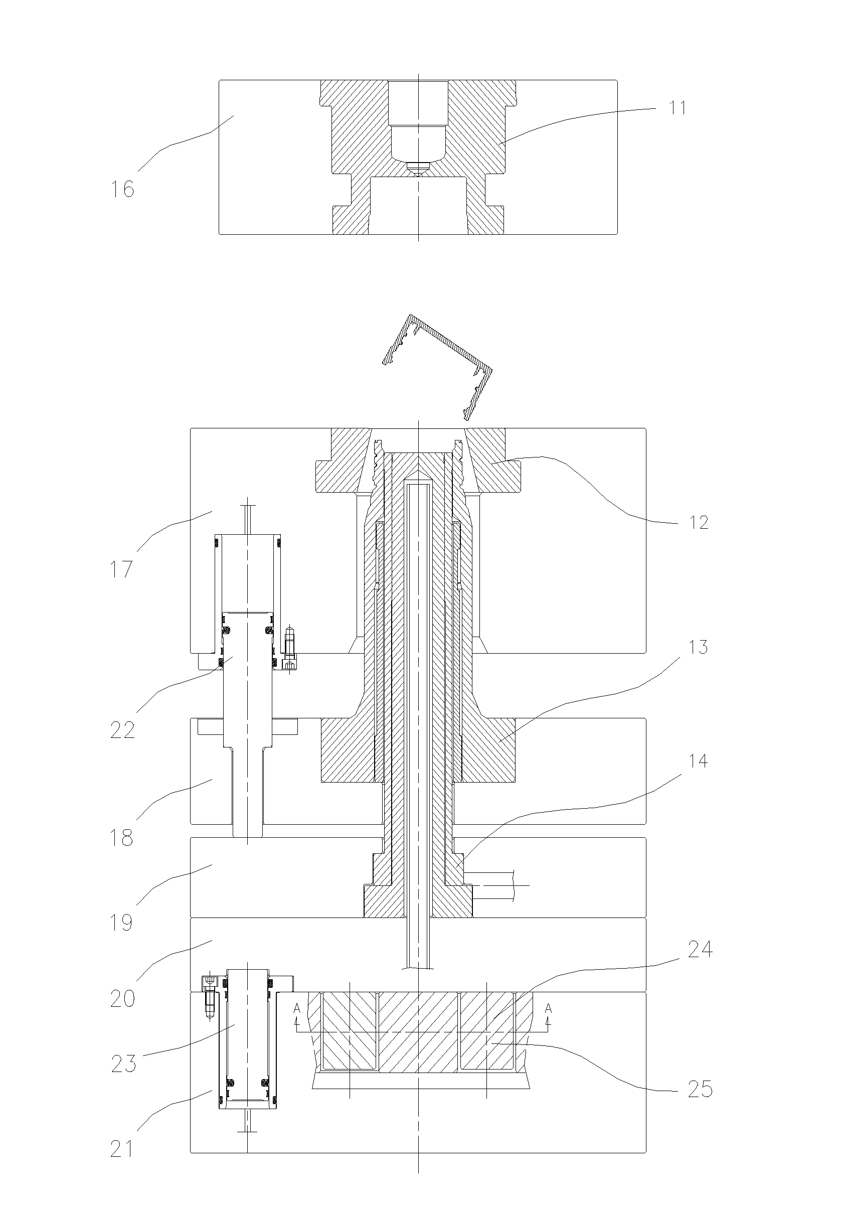
[0033]FIGS. 5-10 show a first embodiment of the present invention. As shown in FIG. 5, a demolding mechanism of a plastic bottle cap mold of the present invention is provided on a movable portion of the plastic bottle cap mold. The demolding mechanism comprises a supporting and place-giving device. The supporting and place-giving device is disposed corresponding to cores in the movable portion which are used for demolding so that each of the cores is fixed at a molding position during injection of a bottle cap and retreats during demolding of the plastic bottle cap mold in order to free the molded bottle cap.

[0034]In particular, the supporting and place-giving device has a structure comprising eight supporting pieces 20 on the movable portion and a backing plate 21 provided with place-giving troughs 22. The supporting pieces 20 are fixed on a back side of a panel 16. A front side of the panel 16 is provided with cores. The backing plate 21 is disposed corresponding to the supporting...

embodiment 2

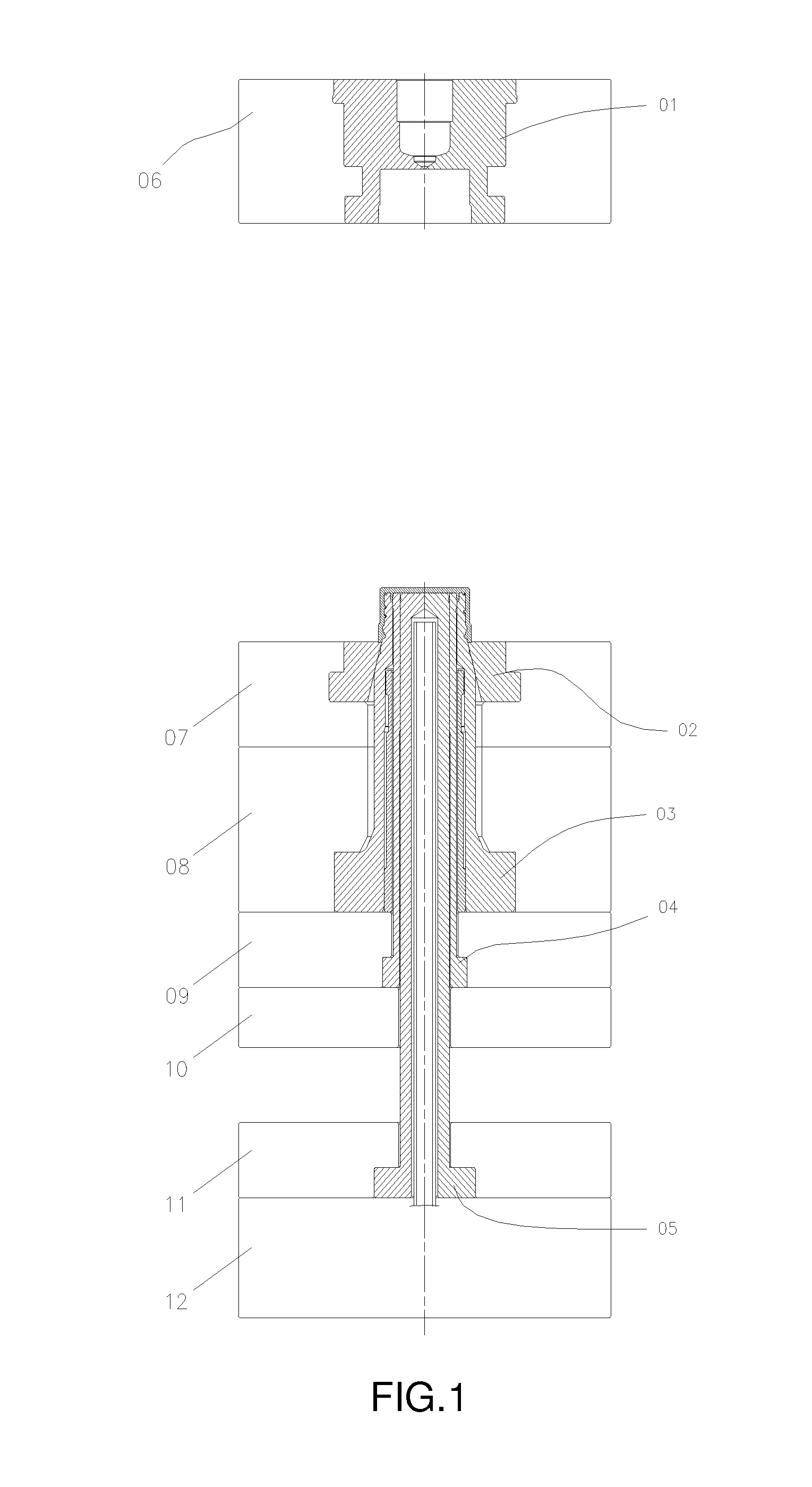
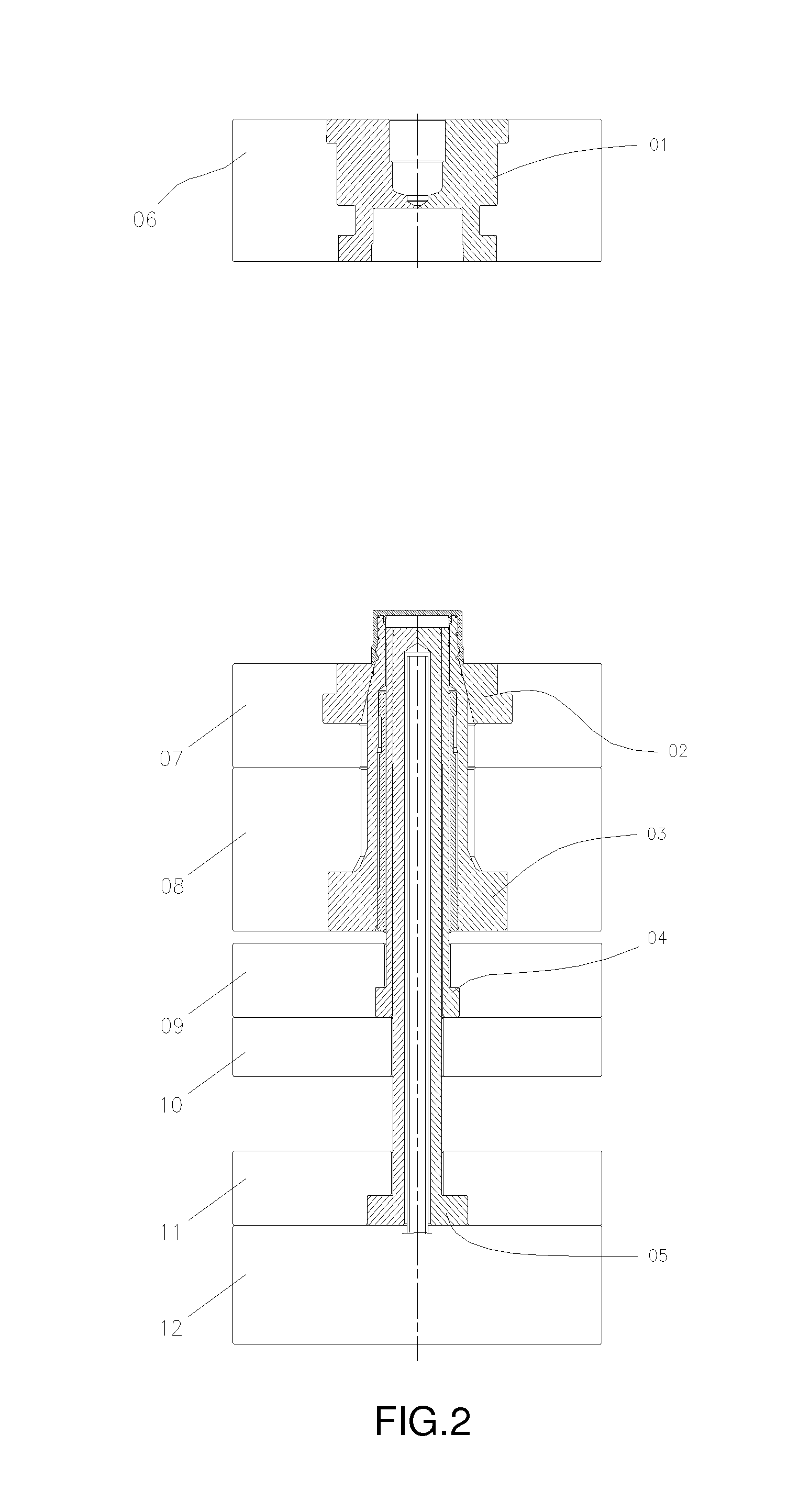
[0043]FIGS. 11-14 show a second embodiment of the present invention. As shown in FIG. 11, when the mold is used for injection of a bottle cap, a space is left between panel 16 and panel 17. The panel 16 receives forces from the hydraulic cylinder 19 (multiple hydraulic cylinder may also be used) so that it can maintain the cores 03, 04, 05 at their molding positions during injection in a way that the cores 03, 04, 05 will not be pushed back by injection pressure. After the bottle cap is molded, the hydraulic cylinder 19 can withdraw its forces and another hydraulic cylinder 18 will then push the panels 14, 15, 16 to cause the cores to retreat backward and to achieve demolding effect for the bottle cap according to the same working principle as in embodiment 1.

embodiment 3

[0044]FIGS. 15-20 show a third embodiment of the present invention. Embodiment 3 is the same as embodiment 1 except for the following features: the supporting pieces 20 as shown in FIGS. 15-16 and the place-giving troughs 22 as shown in FIG. 20 are elongated and vertically parallel to one another. By using a pneumatic cylinder, a hydraulic cylinder or an electrical motor to drive the backing plate 21 to perform linear movement, the backing plate 21 can alternate between the supporting position (FIG. 15) and the place-giving position (FIG. 16).


PUM

PropertyMeasurementUnit
thickaaaaaaaaaa
heightsaaaaaaaaaa
forceaaaaaaaaaa

Abstract

A demolding mechanism of a plastic bottle cap mold provided on a movable portion of the plastic bottle cap mold; the demolding mechanism comprises a supporting and place-giving device; the supporting and place-giving device is disposed corresponding to cores in the movable portion which are used for demolding; each of the cores is fixed at a molding position during injection of a bottle cap and retreats during demolding of the plastic bottle cap mold in order to free the molded bottle cap. A demolding method achieved by the above demolding mechanism is also provided.

Description

BACKGROUND OF THE INVENTION[0001]The present invention relates to a manufacturing apparatus for plastic bottle, and more specifically relates to a demolding mechanism of a plastic bottle cap mold, and a method therefor.[0002]Plastic bottle is a packaging container commonly used in modern daily life. Plastic bottle cap used in conjunction with the plastic bottle is an essential component and is therefore desired desperately in the market. Developments of modern manufacturing technology gradually reduce the size and wall thickness of a manufactured plastic bottle cap as the manufacturing technology becomes more advanced. Plastic bottle cap has also become a plastic product desired in terms of its practicality and its aesthetic nature. Nowadays, manufacturers of plastic packaging container have been improving their product structures and perfecting their manufacturing techniques in order to maintain their competitiveness, and this phenomenon is apparently reflected in shortened manufac...

Claims


Application Information

Patent Timeline
Patent Type & Authority Applications(United States)
IPC IPC(8): B29C45/40
CPCB29C45/4005B29C45/44B29L2031/56B29C45/2602B29C45/4421B29C45/64B29L2031/565B29C45/2618
Inventor LAU, KWONG FAT
Owner LAU KWONG FAT
Why Eureka
Try Eureka