Feed devices for swagable lockbolt collars

a technology of feed device and lockbolt collar, which is applied in the direction of screws, instruments, de-stacking articles, etc., can solve the problems of collar falling off the lockbolt shank, reducing the efficiency of the lockbolt installation process, and affecting the installation process. , to achieve the effect of convenient connection and disconnection

Active Publication Date: 2015-07-02
GAGE BILT
View PDF9 Cites 29 Cited by
  • Summary
  • Abstract
  • Description
  • Claims
  • Application Information

AI Technical Summary

Benefits of technology

[0010]In a second embodiment of the invention hereinafter described, a collar presentation device comprises a cartridge with a spiral-shaped internal collar passage, and a grip which fastens to the cartridge in such a way as to (a) receive collars from the cartridge, and (b) connect a supply of pressurized air to the cartridge to urge collars upwardly through the spiral passage and into the grip where they enter a curved feeder queue that holds the collars for placement onto a lockbolt shank. The cartridge and grip may be easily connected and disconnected by any suitable means, one of which is shown and described below.

Problems solved by technology

As a practical matter, there are several problems that can crop up in the field.
Even if a sticky substance like rubberized cement is used to hold the unswaged collars in place, the swaging process may still cause collars to fall off of the lockbolt shanks before they are swaged.
This not only reduces the efficiency of the lockbolt installation process, but also requires a worker to prevent dropped collars from becoming “foreign object debris” (FOD).
Another problem which often arises in the field is the collection and disposal of lockbolt shank pintails broken off during the swaging step.
Ejected pintails often collect on or around the workpiece or fall on the floor where they present a safety hazard.
Moreover, normal collection further reduces lockbolt installation efficiency.

Method used


Image

  • Feed devices for swagable lockbolt collars
  • Feed devices for swagable lockbolt collars
  • Feed devices for swagable lockbolt collars

Examples


Embodiment Construction

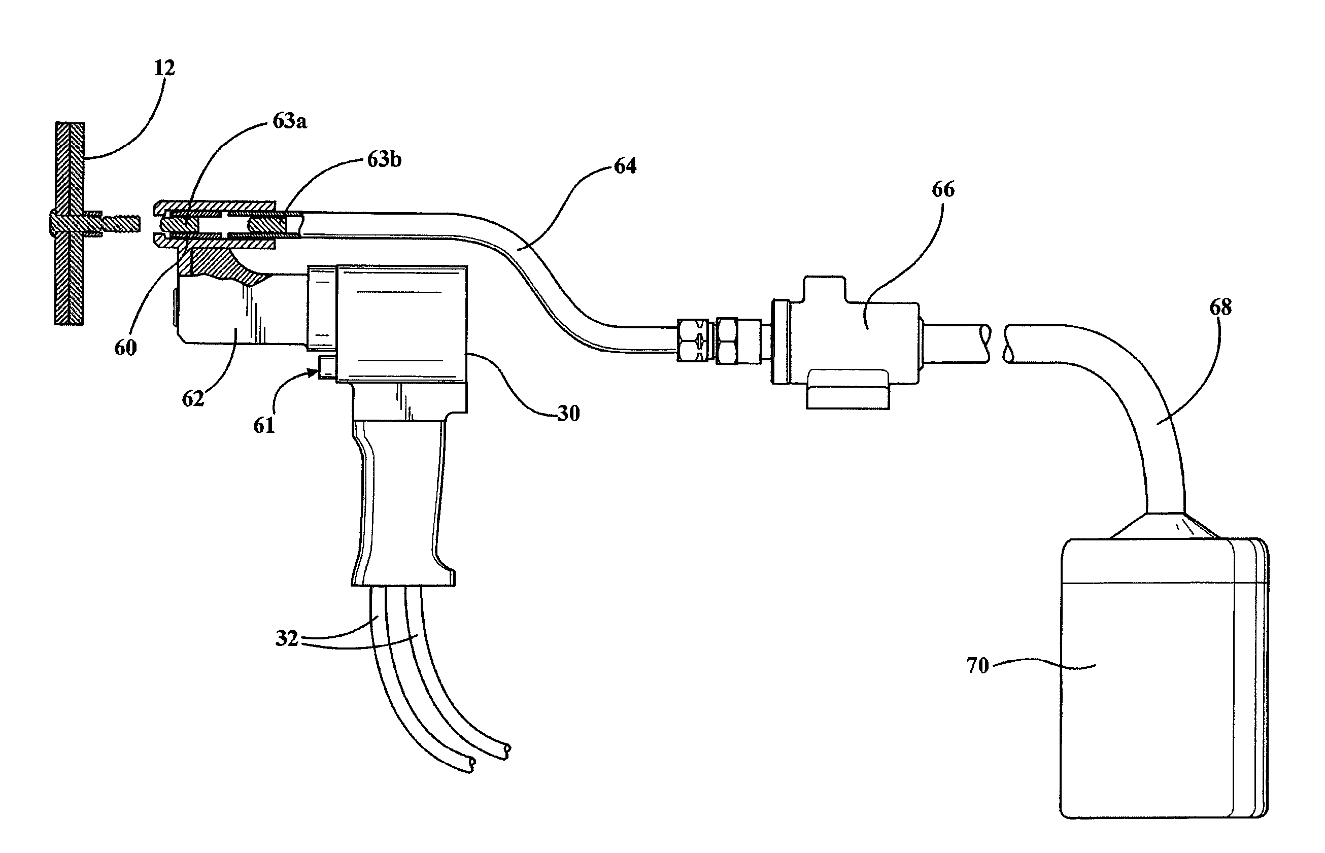
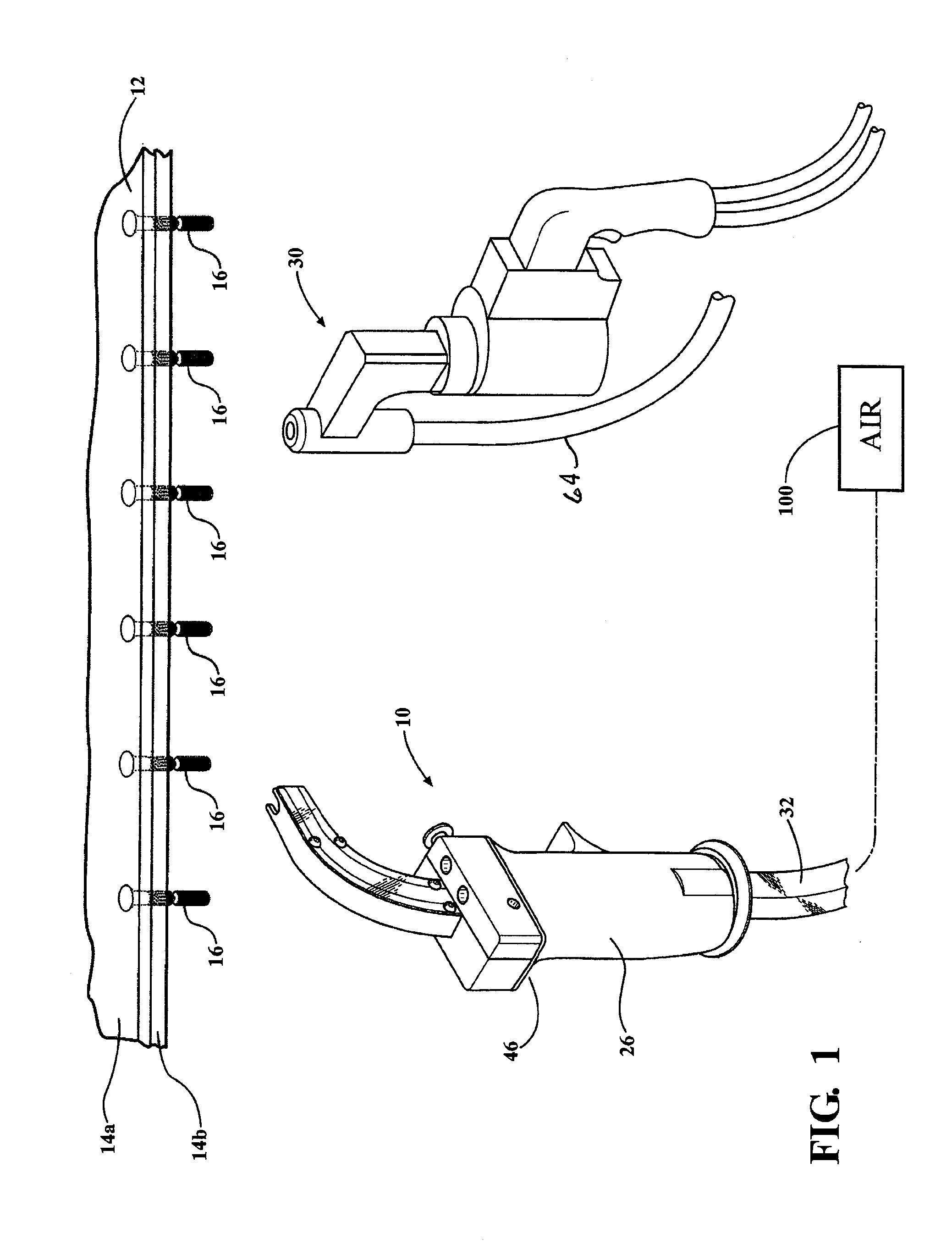
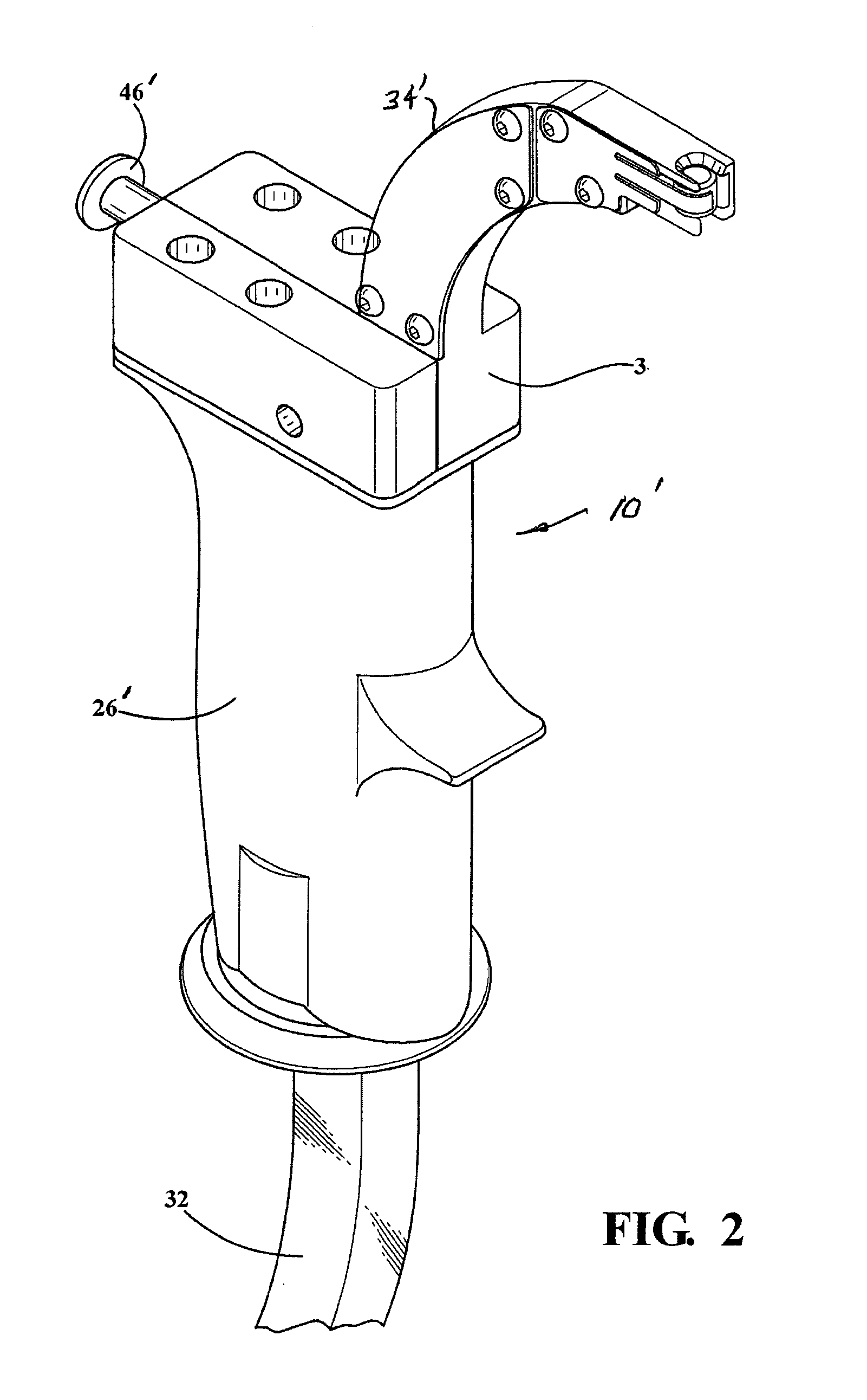
[0026]Referring to the drawings, and particularly to FIG. 1, there is shown a two-part system for installing lockbolts in a workpiece 12 that, in this case, is shown simply as two sheets 14a and 14b of metal to be fastened together. The sheets may, for example, be aluminum sheets. The sheets are joined together by lockbolts 16 of the “pintail” type. The system for installing lockbolts 16 comprises a feeder tool 10 for placing swagable metal collars 28 (FIG. 2) onto the exposed shanks of lockbolts 16, and a swaging tool 30 having a pintail collection feature including a vacuum conduit 64 further described herein with reference to FIG. 6. While the system of FIG. 1 works to best advantage when both tools 10 and 30 are present, tool 10 may be used with any swaging tool, and the pintail collection system associated with tool 30 may be used without the feeder tool 10. Tools 10 and 30 are provided with pressurized air by a regulated supply 100 that may be part of a power unit such as the ...


PUM

PropertyMeasurementUnit
air pressureaaaaaaaaaa
lengthaaaaaaaaaa
transparentaaaaaaaaaa

Abstract

An air-driven feeder tool is provided for presenting swagable collars one at a time for placement on the shanks of lockbolts and thereby made ready for the application of a swaging tool. The swaging tool breaks off a pintail from the lockbolt and a vacuum system draws the broken-off pintails through a vacuum device and into a receptacle for safe disposal. The feeder mechanism comprises a magazine holding a supply of side-by-side collars, a presentation piece holding a short working collars and a worker-actuable trigger mechanism between the two queues for transferring collars, one at a time, from the magazine to the presentation queue. Two embodiments of the feeder tool are disclosed, each with a unique trigger position.

Description

CROSS-REFERENCE TO RELATED APPLICATION[0001]This application is a continuation-in-part of the co-pending U.S. patent application Ser. No. 13 / 744,814 filed Jan. 18, 2013. The entire contents of applications Ser. No. 13 / 744,814 are incorporated herein by reference.FIELD OF THE INVENTION[0002]The invention relates generally to the installation of lockbolt fasteners having shanks adapted to receive swagable collars and more particularly to devices for conveniently presenting collars for placement on lockbolt shanks such that a swaging tool can thereafter be applied to secure the collars to the lockbolt shanks. In addition, a device is provided for collecting lockbolt pintails broken off by the swaging tool.BACKGROUND OF THE INVENTION[0003]Lockbolts of the type having grooved or threaded shanks adapted to receive a swagable metal collar have been known and in widespread use since at least as early as the application date of U.S. Pat. No. 2,521,048 incorporated by reference into expired U...

Claims


Application Information

Patent Timeline
Patent Type & Authority Applications(United States)
IPC IPC(8): F16B39/34B21J15/32B21J15/02
CPCF16B39/34B21J15/326B21J15/022B21J15/105B21J15/32B21J15/38B23P19/003B23P19/005B23P19/006B25B23/06F16B19/05F16B39/284Y10T29/49925Y10T29/49948Y10T29/49956Y10T29/53496Y10T29/535Y10T29/5373
Inventor GODFREY, BRUCE T.LEIGH, BRIAN H.POTTS, TONY P.
Owner GAGE BILT
Why Eureka
Try Eureka