Acoustic transducer in system for gas temperature measurement in gas turbine engine

a technology of acoustic transducer and gas turbine engine, which is applied in the direction of machines/engines, instruments, heat measurement, etc., can solve the problems of introducing uncertainties in relation to temperature calculations for controlling the engine, and the problem of providing temperature measurements of hot working gas upstream of the turbine section

Inactive Publication Date: 2015-07-02
SIEMENS ENERGY INC
View PDF18 Cites 12 Cited by
  • Summary
  • Abstract
  • Description
  • Claims
  • Application Information

AI Technical Summary

Benefits of technology

[0024]In accordance with a further aspect of the invention, a gas turbine engine is provided including an apparatus for controlling operation of the gas turbine engine, and the engine having a boundary structure defining a flow path passing through the engine. The apparatus for controlling operation of the engine comprises first and second acoustic transmitter/receiver devices located on the boundary structure at predetermined axial locations along the flow path. The acoustic transmitter/receiver devices each include an elongated sound passage defined by a surface of revolution having opposing first and second ends and a central axis extending between the first and second ends, an acoustic sound source located at the first end, and an acoustic receiver located within the sound passage between the first and second ends. The boundary structure includes first and second openings extending from outside the boundary struc

Problems solved by technology

Such monitoring systems generally require locating thermocouples at different fixed axial locations along the exhaust flow, which may introduce uncertainties in relation to temperature calculations for controlling the engine as conditions affecting operation of the engine change, such as a varyin

Method used


Image

  • Acoustic transducer in system for gas temperature measurement in gas turbine engine
  • Acoustic transducer in system for gas temperature measurement in gas turbine engine
  • Acoustic transducer in system for gas temperature measurement in gas turbine engine

Examples


Embodiment Construction

[0038]In the following detailed description of the preferred embodiment, reference is made to the accompanying drawings that form a part hereof, and in which is shown by way of illustration, and not by way of limitation, a specific preferred embodiment in which the invention may be practiced. It is to be understood that other embodiments may be utilized and that changes may be made without departing from the spirit and scope of the present invention.

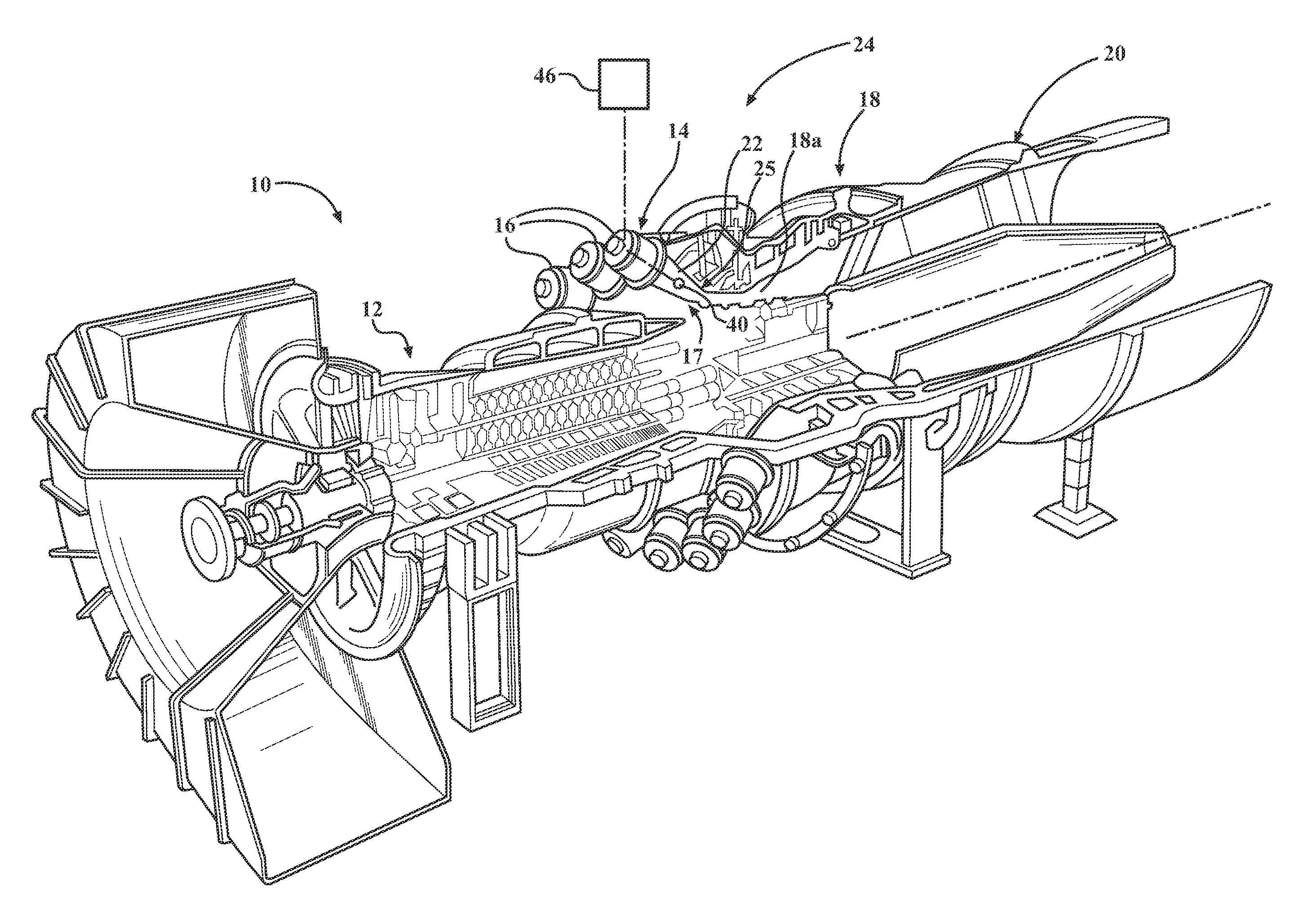
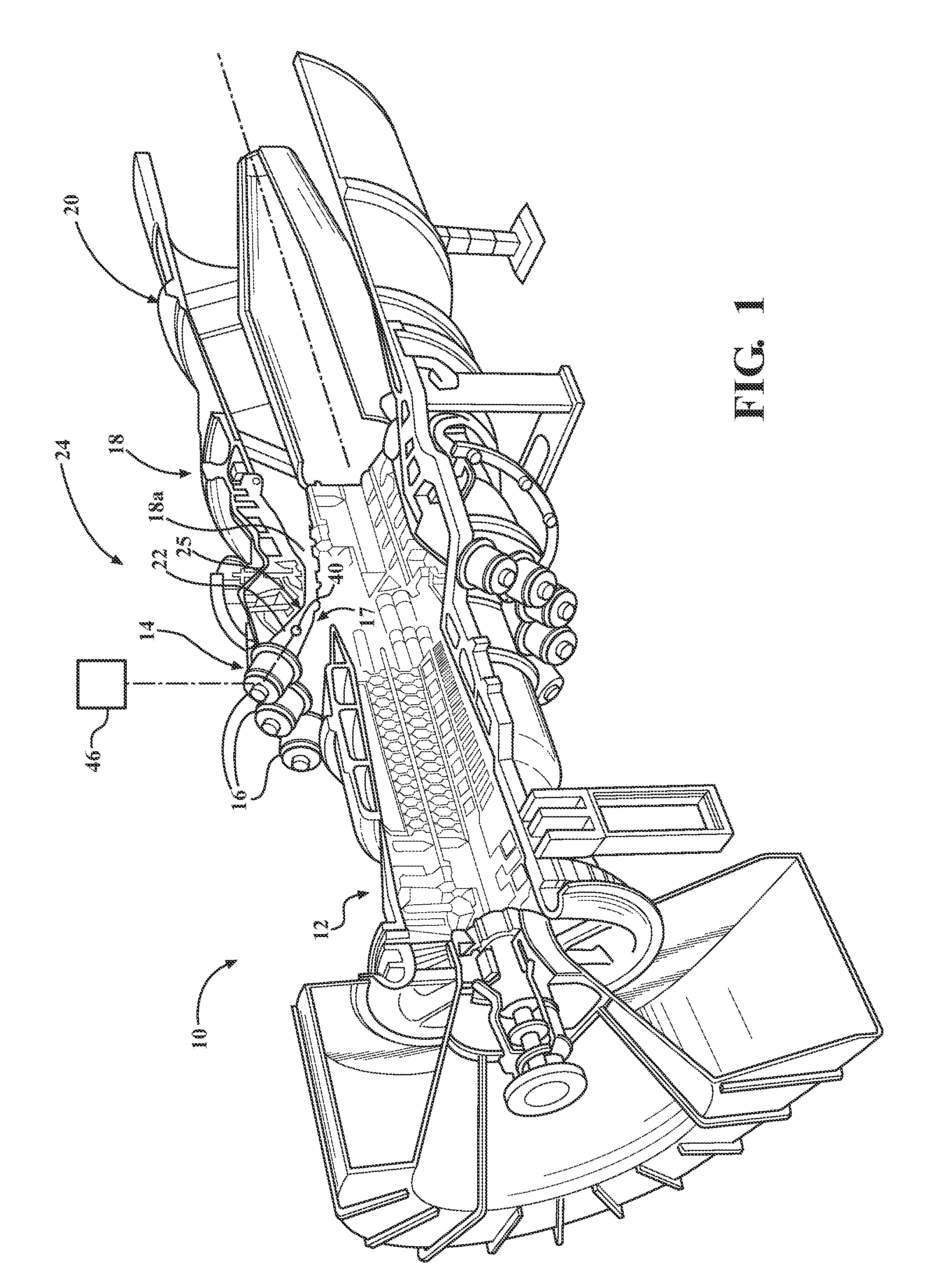
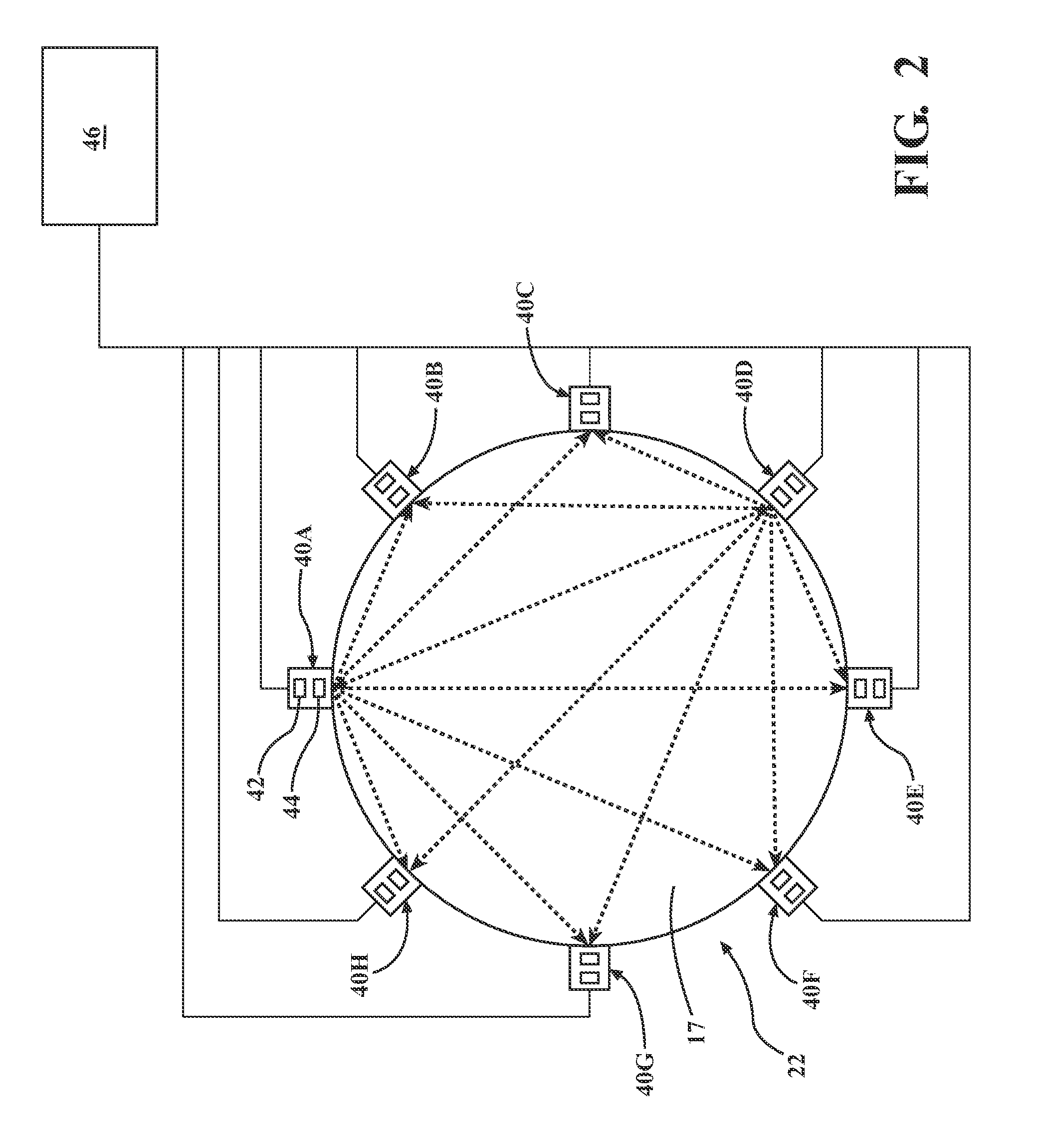
[0039]A temperature measurement apparatus or system is described herein that is configured to be used to continuously monitor high temperature combustion gases, such as may be on the order of 1500° F., as part of an on-line monitoring and control system to be used on a long term basis within a gas turbine engine. In accordance with an aspect of the invention, it has been noted that acoustic pyrometry methods may be implemented to avoid placing temperature probes directly within the hot combustion gas flow, however, background noise assoc...


PUM


Abstract

An apparatus for controlling operation of a gas turbine engine including at least one acoustic transmitter/receiver device located on a flow path boundary structure. The acoustic transmitter/receiver device includes an elongated sound passage defined by a surface of revolution having opposing first and second ends and a central axis extending between the first and second ends, an acoustic sound source located at the first end, and an acoustic receiver located within the sound passage between the first and second ends. The boundary structure includes an opening extending from outside the boundary structure to the flow path, and the second end of the surface of revolution is affixed to the boundary structure at the opening for passage of acoustic signals between the sound passage and the flow path.

Description

CROSS REFERENCE TO RELATED APPLICATIONS[0001]This application is a continuation-in-part of U.S. patent application Ser. No. 14 / 017,386, (Attorney Docket No. 2013P02457US) filed on Sep. 4, 2013, and entitled “NON-INTRUSIVE MEASUREMENT OF HOT GAS TEMPERATURE IN A GAS TURBINE ENGINE,” the entire disclosure of which is incorporated by reference herein.STATEMENT REGARDING FEDERALLY SPONSORED DEVELOPMENT[0002]Development for this invention was supported in part by Contract No. DE-FC26-05NT42644, awarded by the United States Department of Energy. Accordingly, the United States Government may have certain rights in this invention.FIELD OF THE INVENTION[0003]The present invention relates to temperature measurement in turbine engines and, more particularly, to determination of temperature of a hot gas using acoustic measurements in a gas turbine engine.BACKGROUND OF THE INVENTION[0004]Combustion turbines, such as gas turbine engines, generally comprise a compressor section, a combustor sectio...

Claims


Application Information

Patent Timeline
IPC IPC(8): G01K11/24G01K13/02G01M15/14
CPCG01K11/24G01K13/02G01M15/14F02C9/00F05D2270/303G01H1/003G01H3/00G01K13/024
Inventor DESILVA, UPUL P.CLAUSSEN, HEIKO
Owner SIEMENS ENERGY INC
Why Eureka
Try Eureka