
Method, apparatus, system for lane staggering and determinism for serial high speed I/O lanes

Active Publication Date: 2015-07-02
INTEL CORP
View PDF5 Cites 11 Cited by
  • Summary
  • Abstract
  • Description
  • Claims
  • Application Information

AI Technical Summary

Benefits of technology

The patent text discusses techniques for managing lane staggering and differential peaks in high-speed serial input / output (I / O) ports, such as PCI-Express, to ensure proper operation and performance. The technical effect of the patent text is to provide a solution for maintaining the specified range of differential peaks in the PCI-Express serial point-to-point fabric, which can be challenging as the number of lanes and their vendors increase. The solution involves staggering all the lanes in a staggered fashion to absorb the differential current and prevent damage to the end card circuits. The patent text also discusses the use of process flow diagrams and speed state diagrams to aid in the development and testing of the techniques.

Problems solved by technology

However, if all the lanes of a specific configuration enter or exit an idle state simultaneously, the differential peak can be large, exceeding this limit.
As PCIe compliant computing systems continue to increase the number of communication lanes, the problem becomes more challenging.
As the PCIe lanes shrink to 22 nm and below, the differential peak can exceed 20 mV if all the lanes enter or exit an idle state simultaneously, which may damage the end card circuits.
Approaches for maintaining the differential peak within the specification, such as adding large capacitors on board lanes to absorb the differential current, are not sufficient for interconnects with larger numbers of lanes, and where the technology has shrunk to 22 nm and below.
Further, as more functionality, like PCIe, gets integrated into processors, it becomes increasingly difficult to replicate errors found in the post debug cycle.
However, PSMI works with deterministic protocols, and PCI-Express is not deterministic.

Method used


Image

  • Method, apparatus, system for lane staggering and determinism for serial high speed I/O lanes
  • Method, apparatus, system for lane staggering and determinism for serial high speed I/O lanes
  • Method, apparatus, system for lane staggering and determinism for serial high speed I/O lanes

Examples


example 1

[0074]A method of debugging a computing system using a non-core system register, or register means, is described herein. The register means may include a register of accessible by a system agent of the computing device, wherein the system agent is a non-core component of the computing device. Debug data may be generated at agents in the computing system including agents of firmware devices and agents of system software such as drivers of the computing system. The agents have access to the register means, and the register may accessible via a observability fabric means, such as a system interconnect fabric, to enable debug data to be stored in a memory unit and analyzed by debug software and / or hardware. The observability fabric means may include an on-chip analyzer configured to compress and time stamp the debug data.

example 2

[0075]An apparatus is described herein. The apparatus may be configured to receive debug data at a non-core register, or register means. The register may be configured to record the debug data and a memory unit, or memory means, may be configured to receive the debug data via an interconnect fabric, such as an observability fabric, or observability fabric means. The memory unit may store the debug data and may be accessible by debug software and / or hardware to determine the source of the debug data. In embodiments, the interconnect fabric may include analyzer logic, such as an on-chip analyzer, to compress and timestamp the data to be received at the memory unit. The agents may include driver agents of an operating system and / or firmware agents of microcontrollers communicatively coupled to the system. In embodiments, the agents, such as the firmware agents, may have access to the register via a computing system interconnect means, such as the observability fabric discussed above.

example 3

[0076]A computing device is described herein. The computing device may include a driver agent, a firmware agent, and a register means. The driver agent may be driver logic that is accessible by driver code to be executed on a processing element. The driver agent is associated with an operating system of the computing device to generate debug data. The firmware agent may be controller logic to provide second debug data for one or more controllers. The register means, may be a register, or a storage element, disposed in a non-core portion of the computing device, wherein the firmware agents and the driver agents may provide debug data to the register. The register may be configured to record the debug data and a memory unit, or memory means, may be configured to receive the debug data via an interconnect fabric, such as an observability fabric, or observability fabric means. The memory unit may store the debug data and may be accessible by debug software and / or hardware to determine t...


PUM


Abstract

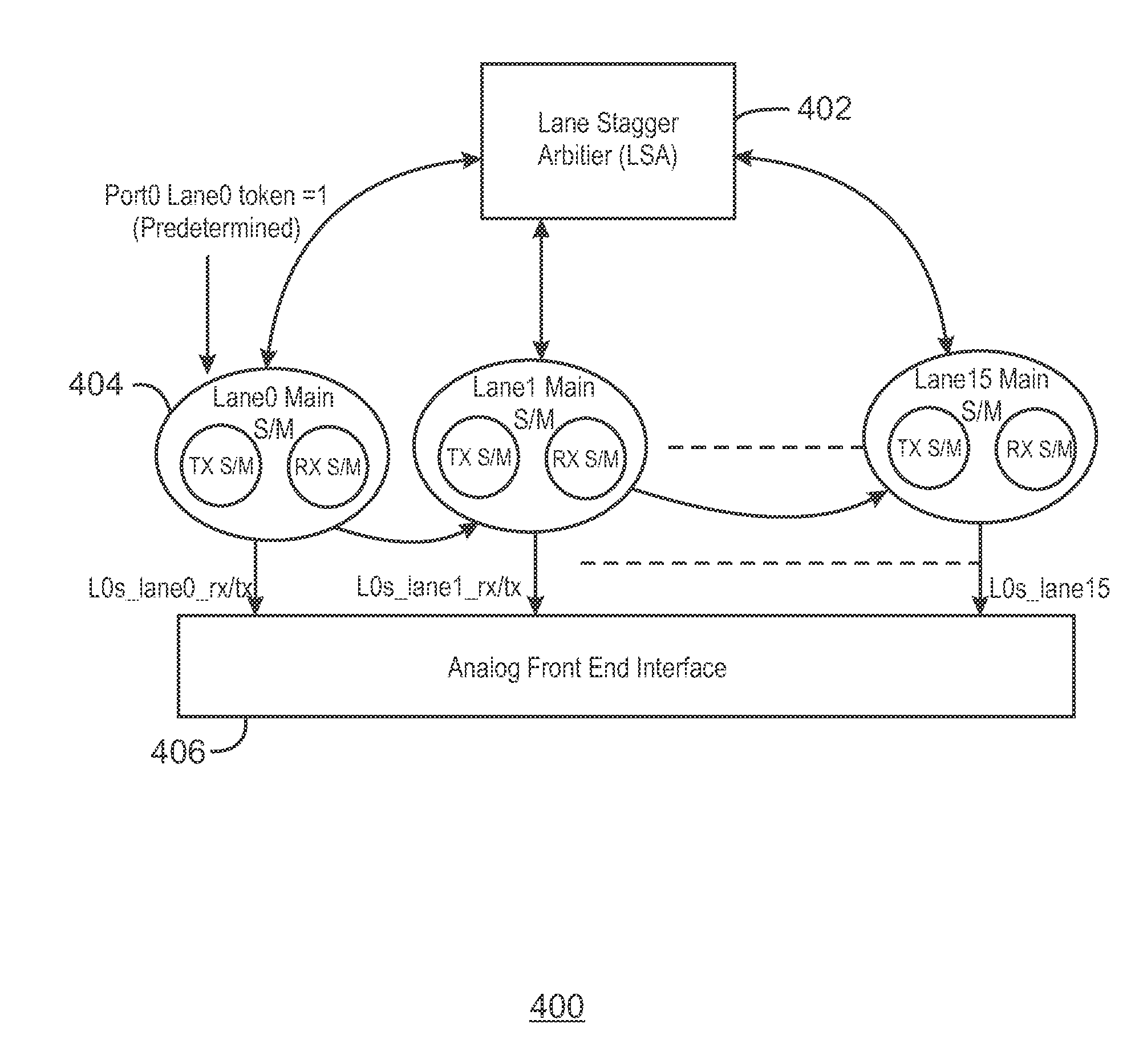
A method of staggering lanes in a peripheral component interconnect express (PCI-Express) port is described herein. The method includes initiating the port to enter or exit an electrical idle state. The method also includes forwarding a token to a predetermined lane of the port. Additionally, the method includes turning the predetermined lane ON or OFF by indication to an analog circuit interface. The method also includes forwarding the token to a neighboring lane when a staggering interval timer elapses.

Description

TECHNICAL FIELD[0001]This disclosure pertains to lane staggering and determinism for serial high speed I / O lane architectures.BACKGROUND ART[0002]Some examples of architectures with serial high speed I / O lanes include the serial advanced technology attachment (SATA), universal serial bus (USB), and peripheral component interconnect express (PCI-Express or PCIe), among others. The PCI-Express interconnect architecture enables components and devices from different vendors to inter-operate in an open architecture. This architecture spans multiple market segments, from clients to servers. The PCIe uses numerous lanes for communication between components, and operates according to a PCIe specification. The PCI-Express Specification states that the Electrical Idle differential peak output voltage per lane (VTX-IDLE-DIFF-AC-p) is not to exceed 20 mv (p-p). However, if all the lanes of a specific configuration enter or exit an idle state simultaneously, the differential peak can be large, e...

Claims


Application Information

Patent Timeline
IPC IPC(8): G06F1/32G06F13/40
CPCG06F13/4027G06F1/3253G06F1/3278Y02D10/00Y02D30/50
Inventor BHARADWAJ, PRAHLADACHAR JAYAPRAKASHDAS SHARMA, DEBENDRAPOLADIA, HARSHITGADEY NAGA VENKATA, KANAKA LAKSHMI
Owner INTEL CORP
Learn More